wuchy143
Member
Hi All,
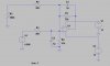
I'm trying to simulate the effect of the 500k Ohm output impedance to my amplifier. The D/A is the MCP4921. I did it by just putting in a 500k Ohm(from datasheet) to ground on the input to my " - " terminal on my OPA. Is this a viable/appropriate way of simulating a high output impedance in LTSpice?
Circuit below.