Continue to Site

Welcome to our site!

Electro Tech is an online community (with over 170,000 members) who enjoy talking about and building electronic circuits, projects and gadgets. To participate you need to register. Registration is free. Click here to register now.

  • Welcome to our site! Electro Tech is an online community (with over 170,000 members) who enjoy talking about and building electronic circuits, projects and gadgets. To participate you need to register. Registration is free. Click here to register now.

simpliest 555 based dc-dc isolated converter . (no need for regulation)

Status
Not open for further replies.

settra

Member
Hello forum! I want to make an isolated DC-DC converter with 12V input. the thing is :
I dont have much experience, so i am looking for the simplest method possible..
Where i leave i dont have access to many IC's, so i need to make it happen with a 555 chip...

I Know this is not a very good way to do it, but in my project i just need to have an Isolated DC source..
i am totally fine with having to use a voltage regulator after the flyback, and i dont care if the Vout will be the same as Vin, or if it will be fixed 5V !
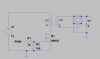
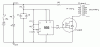
I have found this schemantic :

Which i thing is used to boost DC. Will it work?? What to i have to change in order for Vout = Vin, or Vout= 5V?? also, will 1-1 Transformer work??
Or is it not possible at all?? thanks !!
 

Attachments

  • HV_power_supply_small.gif
    HV_power_supply_small.gif
    4.5 KB · Views: 8,455
The output of the transformer is an AC squarewave, not DC. To make DC from the squarewave you must rectify and filter it. Then if the DC output voltage is high enough it can feed a voltage regulator IC circuit.
 
Why bother with the IC if no regulation is needed? Just use a two transistor push pull oscillator for the primary side and a simple rectifier circuit for the secondary side.
 
Are you sure you want to built this 555 circuit? You can buy one for $3.26 I built this same circuit.

Here is a photo of the one I built 20+ years ago. I used a 2n3055 transistor instead of a mosfet. The aluminum plate you see all the parts attached to is also my heat sink for the transistor. I have a car ignition coil in the photo. The car ignition coil does not work well above about 10KHz but it will make a spark just as long as a flyback transformer, about 3/8" long. The GIANT filter cap I used is over kill. Dont go over 15vdc it will kill the 555 timer, play it safe stay below 14vdc. The nice thing about the variable frequency is, you can dial in maximum spark length for the HV transformer. Max spark length on the ignition coil is about 5KHz. Max spark length on the flyback is much higher frequency. The flyback does not work well at low frequency.

**broken link removed**

$_57.JPG


003_zps87ba4be2.jpg
 
Last edited:
Gary, the OP is looking to get ~5V out; not 50kV ;).
 
Gary, the OP is looking to get ~5V out; not 50kV ;).

Look at his circuit drawing it shows a flyback transformer. That is the typical transformer all beginners use for HV= high voltage. His circuit also says, HV power supply. YOU might be right he is talking about 5v regulated after the flyback? That makes no sense if all he wants is 5v regulated he can have that without the flyback. His circuit drawing is identical to the one I built.
 
Last edited:
i indeed look for 5v :) As i mentioned, i dont know half the things required for this thing to be done.... and i would buy a complete circuit, or even an IC if i could get my hands on one... :) This is why i posted the circuit to you guys :D becouse i dont know if its what i need!

Why bother with the IC if no regulation is needed? Just use a two transistor push pull oscillator for the primary side and a simple rectifier circuit for the secondary side.

This seems like just what i need! can you post a simple circuit for that?? thanks!
 
Think I agree with TCMtech - a push-pull or a half bridge would probably suit the problem better. I'm no expert, but a flyback design is typically used to boot voltage, often by a high ratio. You'll probably get a better power transfer using one of these other designs, where the transformer ratio will set the output voltage (that's not the case for a flyback converter).
 
2000px-Push-pull_converter_schematic.svg.png

I think that this is the simpliest push-pull i could find... As i understand, the outpout voltage depends only on the transformer ratio, and not on the Frequency and on-off time??? On the above circuit, where is the Vcc and GND connected?? :p
Also, as siwtches, can i use the PWM of a microcontroller, with two nMOS and a logic inverter?? (i can easier use an ATtiny's PWM, than 555... :p )
 
The input to the switches is DC, the polarity does not matter because the switches alternate it into AC.
It will be difficult to make two alternating switches (they are not simply on-off, instead they are a change-over switch), it is much simpler to use a 555 oscillator to feed the transformer.
A 50Hz or 60Hz transformer works poorly at high frequencies. A high frequency transformer works poorly at low frequencies.
If the on time or off time is too short then it will appear as a high frequency and a low frequency transformer will pass it poorly.
 
0.2A is the absolute maximum output current of a 555. Better to aim for much less switching current than that.
The most difficult thing to source is likely the transformer. What is available to you?
Do you want a converter that switches at ~ mains frequency (if a mains tranny is all you can get) or more efficiently at >20kHz?
 
Here's a simple two transistor inverter circuit.
The oscillation frequency is determined by the saturation characteristics of the transformer. The oscillator changes states when the transformer core starts to saturate due to the primary magnetizing current.
The transformer turns ratio can be whatever you need to get the desired output voltage.
 
hello forum. thnx to your help i have made something like this working (although its not what we discussed, and it's faaaar from efficient:p )

The transformer is 1-1 ratio. Its a transformer i salvaged from old electronics, so i have no idea about what freq its for :p
The controller , PWM's the mosfet at 31Khz ! The voltage input is 12v, and the output is about 9v :p So, a couple of questions :D
1)what circuit do i need, to change the controller for a 555 timer??
2)what can i do to improve it noise-wise ?
3)what do i need to increase the output current??
4)you think that the voltage drop happens, cause of bad freq used on the transformer, or because of bad topology?? (btw the mosfet heats up ALLOT :D )
 

Attachments

  • isolated dc.png
    isolated dc.png
    11.8 KB · Views: 1,048
The value of the 1k resistor feeding the high capacitance of the Mosfet's gate causes the Mosfet to turn on and turn off slowly causing heat. Use 22 ohms instead but maybe whatever you have driving it cannot supply enough current to quickly charge and discharge the gate capacitance. Maybe you have the 10k resistor very very slowly turning off the Mosfet so it is ramping instead of switching.

A 555 can drive the 22 ohm resistor feeding the gate of the Mosfet.

Nobody knows anything about your transformer so maybe its resistance or your high input frequency frequency reduces the voltage and current. Of course the bridge rectifier reduces the output about 2V.
 
You don't want any flyback circuit. You just want a self oscillating push-pull arrangement. You can wind the transformer yourself on a ferrite rod. Give it 5 turns per volt and a centre-tapped primary.
2 x BC338 Base resistor 2k2 and some speed-up capacitors. You will get 200mA at 40kHz
 
Always good to hear a success story.
 
Status
Not open for further replies.

Latest threads

New Articles From Microcontroller Tips

Back
Top