Continue to Site

Welcome to our site!

Electro Tech is an online community (with over 170,000 members) who enjoy talking about and building electronic circuits, projects and gadgets. To participate you need to register. Registration is free. Click here to register now.

  • Welcome to our site! Electro Tech is an online community (with over 170,000 members) who enjoy talking about and building electronic circuits, projects and gadgets. To participate you need to register. Registration is free. Click here to register now.

Simple Stereo To Mono Circuit

Status
Not open for further replies.

StudentSA

Member
Hi,

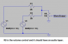
Please can you advise if the below passive circuit would work to convert a line out Left and Right audio to Mono and allow for volume reduction?

Stereo2Mono.JPG


V1 and V2 are left and Right channels, R1,R2 are 10k Resistors, R3 is a 10k variable potentiometer (could not find the variable resistor symbol)
For R3 The mono output is actually the wiper with side 1 to the R1R2 and side 2 to ground.

Thanks,
 
Last edited:
What load impedance does the right end connect to? The load impedance will create a voltage divider against the 20K source impedance looking back at V1/V2.
Nominally, to get no more than a 6db insertion loss, R1, R2, and R3 should be a bit less than the input impedance of whatever is to the right.
 
Are you trying to use R3 as a volume control? Then it should be a voltage divider, not in series. Then R3 should have a value more than R1 and R2. A headphones output has a low resistance so reduce the resistance of R1 and R2 to 2k each.
I changed your schematic to show a voltage divider volume control.
 

Attachments

  • mono with volume control.png
    mono with volume control.png
    60.2 KB · Views: 783
Thank you, Yes I wanted R3 to be a variable resistor as a "volume control".

So the source of the audio is from a line out of a audio system. The right(MonoOutput) is a USB sound card mic in.

Thank you audioguru for the suggestion of dropping R1 and R2 to 2K and using a taper. I will create this circuit and test.
 
First you said the source is a headphones output (low impedance). Now you say line outputs (fairly high impedance). I do not know if your line outputs can drive my fairly low value of R1 and R2.
Microphone level output? Then you need an attenuator and you should TELL ALL in your first post.

Line level is a few hundred millivolts. Mic level is maybe only 10mV so without an attenuator the volume control must be turned down almost to zero and it will be difficult to smoothly adjust its level. Using a 10k volume control maybe R1 and R2 should be 200k ohms.
 
Apologies, So the line out is fed in through a 3.5mm headphone jack type connector. My objective is to firstly "MONOtise" (if thats even a word) the audio. Then I want to set the volume once off and leave it. So I will not be constantly adjusting the pot. I will edit my first post as you rightly pointed the error.
 
With R1 and R2 as 200k resistors feeding the 10k volume control then they make the attenuator that is needed. Then the volume control will be set correctly near half-way so you can turn it up or down from there.
 
Thanks AudioGuru,

Here is the built circuit, I will only be able to test tomorrow and advise:

IMG_20151205_111335.jpg
IMG_20151205_111348.jpg


Kind Regards,
StudentSA
 
Your very cheap volume control does not look like it has an "audio taper" that is logarithmic like our hearing's sensitivity to loudness.
To see if it is linear or if it has an audio taper then set it to half-way and measure the resistance from the slider to one end. If it is linear then it will measure half the total resistance. If it has an audio taper then the resistance from its slider to ground will be 10% to 20% of its total resistance.
 
Since you can SIM, the issue your missing is the input and output impedances.

The "normal" way to find these is to create a known signal (e.g. sine wave) of a know low Z and then insert a variable resistor in series and adjust the variable resistor such that it's half. Measure the resistor. This will be the input Z,

Specs may or may not be listed. You have to include these.
 
audioguru, cheap yes, but I like to look at it as "fit for purpose" :)
I tested the 220k version on the circuit and it worked except the audio is now a tad too soft.
I then decided to change the circuit such that the input impedance is configurable... like so (again fit for purpose solution):
Configurable_Impedance.jpg

Notice how the resistors now plug in :)

Im hoping that using a somewhere between 100k and 150k should do the trick, however unfortunately I can only test again next weekend.

@KISS, I unfortunately don't have the equipment or the access (to the sound system) for that kind of testing. Best way presently for me is guestimate.
 
Does your linear trimpot perform well enough as a volume control? From its minimum setting to only 10% of its maximum setting the volume will increase a lot. From halfway to maximum setting the volume will change only a little. A logarithmic audio taper volume control will smoothly adjust the volume correctly.
 
Hi AudioGuru, I did not have taper pots on hand, I have ordered a few (**broken link removed**) that should come this week.
However for now, the application of this device is, set once, tape up and forget.

Thanks again for the help on this "simple" circuit.
 
Status
Not open for further replies.

Latest threads

New Articles From Microcontroller Tips

Back
Top