Continue to Site

Welcome to our site!

Electro Tech is an online community (with over 170,000 members) who enjoy talking about and building electronic circuits, projects and gadgets. To participate you need to register. Registration is free. Click here to register now.

  • Welcome to our site! Electro Tech is an online community (with over 170,000 members) who enjoy talking about and building electronic circuits, projects and gadgets. To participate you need to register. Registration is free. Click here to register now.

Simple regenarative walkie talkie: modification

Status
Not open for further replies.

Willen

Well-Known Member
Hi,
Maybe many discussions have been allready done in the topic in forums, and it seems it's the most laughed projects by engineers (or ignored). I am doing it as an hobby purpose to know that how simple thing can do the job.

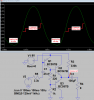
There's a schematic attached below. I collected two popular walkie talkie (popular in google image search) circuits and mixed the features. I selected Xtal oscillator from 'A' circuit and audio amplifier from 'B' circuit and prepared circuit 'C' as shown.

Selected Xtal oscillator to get stability (becoz I do not have frequency meter) and selected the audio amplifier because I do not have access audio transformer shown in 'A' circuit.

Starting question is: What about the C circuit? I wish the C also works same as A and B.
 

Attachments

  • My modified version of transceiver.gif
    My modified version of transceiver.gif
    48.4 KB · Views: 1,321
Ought to work, Willen.

Although, "C" won't have a volume/squelch control. You could, of course, add one.
 
I hate it when they don't show the dots on schematics...
 
Hi,

Then there's 'no joint' around antenna as I indicated in schematic C, isn't it?

Another- the oscillator stage is supplied by audio signal, DC variation voltage actually, which seems low volts. Then the oscillator might get low power to transmit in nice distance. This current version might not transmit at least a distance more than 30 meter? Adding a RF booster lets say 2N3904 based simple one, how can we go? If we couple the antenna with a capacitor and added the RF booster, sure I could amplify the Tx's output signal at least more than 100 meters (not illegal) BUT I suspect while receiving. Need complicated design?
 
Then there's 'no joint' around antenna as I indicated in schematic C, isn't it?
upload_2016-2-18_8-48-22.png

You are correct. There is "no joint".

The "C" circuit represents a simple AM transceiver, i.e., in transmit mode, the audio amp output becomes the variable Vcc of the crystal controlled oscillator circuit. This provides for the amplitude modulation of the oscillator.

You could add the booster you suggest, but to do so would then require (as you noted) additional design to accommodate the receive function using the existing circuit's use of a single antenna. For my part, the effort required for that is not worth the very modest gain in transmitting power.

Now, I suppose you could gain some additional power benefit by simply using a higher Vcc (12 VDC, for example).
 
Last edited:
I simulated the audio power amplifier. It is pretty bad with only 200mW of output power and very high crossover and clipping distortion. I used "B" transistors that have a narrow range of hFE. Transistors with higher or lower current gain might produce even more distortion. I added an input resistor R5 so there is some negative feedback through R3 like in the radio circuit.
If the output transistors get warm then they will conduct more current then the crossover distortion will disappear but the higher current will cause more heat which causes higher current which causes more heat which results in melt down.
 

Attachments

  • power amplifier.png
    power amplifier.png
    28.3 KB · Views: 283
Hi Ag,
Yes, I was thinking about the audio amplifier. Once I made an amplifier same as above for computer speaker and with 7809, the pull-push transistors melt down with full volume! Input is very low here, so I wish it will not melt down here. But again worrying for higher current drain. Maybe do I need to use series resistor in the pull-push trasnsistor? Though, I am ready to accept horriable distortion from the toy. I want to see it to transmit and receive in pretty enjoyable range. (Sure, it will melt down if I used 12V supply as cowboybob said, however transmitting power would almost double.)

Another most interesting, how can I add a RF booster leaving Rx antenna too?
 
An RF booster? And also maybe a real much more sensitive and selective receiver? Then it will not be a cheap and simple child's toy anymore.
 
An RF booster? And also maybe a real much more sensitive and selective receiver? Then it will not be a cheap and simple child's toy anymore.
I do not want sensitive and selective tuned receiver. If I could just add a RF booster for just transmitting purpose, same as MOD 4 has, then it would be enjoyable to me. :)
 
You could add an RF power amplifier that is switched between the toy transmitter and the antenna when transmitting.
 
Then is seems a bigger set of switch. Four sets of switch is already used.

About coil (transformer?): There's a Xtal in the base to generate carrier frequency. However there's a tuning ferrite slug at the collector.

-Why do we need to tune the transformer?

There are no phase dots, I think it's not critical.
 
Impedance matching.
 
The output transformer is tuned for the maximum output level because it resonates with the antenna and 15pF capacitor.
The phase of the transformer might cause feedback from the antenna to the circuit if it is wrong.
 
The output transformer is tuned for the maximum output level because it resonates with the antenna and 15pF capacitor.
The phase of the transformer might cause feedback from the antenna to the circuit if it is wrong.
May I see correct phase dots in the transformer?
 
May I see correct phase dots in the transformer?
In this case you don't care about phase, so dots are left off as it is irrelevant.
 
A manufacturer of a walkie talkie will design one prototype pcb and try it. If it works then they make 100 and if they work they make millions. If the prototype does not work then the try a pcb with the transformer wired with the opposite phase.
 
Status
Not open for further replies.

New Articles From Microcontroller Tips

Back
Top