Pax Writer
New Member
Hello Experts
I'm back with one more, probably silly, question (although this time a little more thought-through).
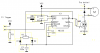
I'm building a small PWM-motor controller based on an NE555 with adjustable duty-cycle on the primary output, which in this case is pin 7 due to the physical construction of the output and discharge pins.
Anyway, the NE555-parts works fine, but of course I ran into some trouble with the MOSFET controlling the GND-connection to the motor.
I can control motor speed to a very small degree, but the MOSFET doesn't seem to close properly. When I measured it with my old scope, it showed only very small voltage variations on the source-pin.
This is the first time I'm using a MOSFET, but I suspect that maybe D and S should be switched to get a clear GND-connection for the voltage on G to "compare" to. Am I off on a wild goose chase here?
As a note I might add that VCC is ~11.3V. D3 is in place because the battery will also drive a heavily loaded brushed DC-motor when the application is complete, and I was hoping that the occasional drops in supply voltage could be avoided by placing the diode in the supply path and let C4 and C1 stabilise the voltage on the cathode-side of D3 when the battery is on peak load every 5ms or so.
The MOSFET, as you can see from the attachment is an IRF3205 which should be able to conduct 20-25A of current even if VGS is only 10V... But again I might have read the data sheet wrong, so feel free to correct me.
Why do you think the MOSFET doesn't switch properly?
I stand by to be educated")
Thanks in advance.
Pax
I'm back with one more, probably silly, question (although this time a little more thought-through).
I'm building a small PWM-motor controller based on an NE555 with adjustable duty-cycle on the primary output, which in this case is pin 7 due to the physical construction of the output and discharge pins.
Anyway, the NE555-parts works fine, but of course I ran into some trouble with the MOSFET controlling the GND-connection to the motor.
I can control motor speed to a very small degree, but the MOSFET doesn't seem to close properly. When I measured it with my old scope, it showed only very small voltage variations on the source-pin.
This is the first time I'm using a MOSFET, but I suspect that maybe D and S should be switched to get a clear GND-connection for the voltage on G to "compare" to. Am I off on a wild goose chase here?
As a note I might add that VCC is ~11.3V. D3 is in place because the battery will also drive a heavily loaded brushed DC-motor when the application is complete, and I was hoping that the occasional drops in supply voltage could be avoided by placing the diode in the supply path and let C4 and C1 stabilise the voltage on the cathode-side of D3 when the battery is on peak load every 5ms or so.
The MOSFET, as you can see from the attachment is an IRF3205 which should be able to conduct 20-25A of current even if VGS is only 10V... But again I might have read the data sheet wrong, so feel free to correct me.
Why do you think the MOSFET doesn't switch properly?
I stand by to be educated
Thanks in advance.
Pax