Electro Tech is an online community (with over 170,000 members) who enjoy talking about and building electronic circuits, projects and gadgets. To participate you need to register. Registration is free. Click here to register now.
Welcome to our site! Electro Tech is an online community (with over 170,000 members) who enjoy talking about and building electronic circuits, projects and gadgets. To participate you need to register. Registration is free. Click here to register now.
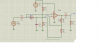
R10, R11 and C3 create a "virtual ground" so the opamp can be operated on a single-supply. It is a non-inverting gain stage, with a gain of (1+39/10). Capacitively coupled, in and out. Input impedance, ~33K.
Not a very good circuit. I would do the bias circuit differently so the power supply consumption would be much lower, like this:
Hi Mike ML,
The original circuit uses the 1uf capacitor to be a low impedance to ground for the 10k feedback resistor plus it filters any power supply ripple from the bias voltage. Your circuit does not filter the bias voltage.
I would use one capacitor to be the low impedance to ground for the 10k feedback resistor and another capacitor as the filter for the bias voltage.
This site uses cookies to help personalise content, tailor your experience and to keep you logged in if you register.
By continuing to use this site, you are consenting to our use of cookies.