Continue to Site

Welcome to our site!

Electro Tech is an online community (with over 170,000 members) who enjoy talking about and building electronic circuits, projects and gadgets. To participate you need to register. Registration is free. Click here to register now.

  • Welcome to our site! Electro Tech is an online community (with over 170,000 members) who enjoy talking about and building electronic circuits, projects and gadgets. To participate you need to register. Registration is free. Click here to register now.

Simple Op-Amp Filter

Status
Not open for further replies.

ThermalRunaway

New Member
Hi Everyone,

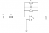
Please see attached file for a simple Op-Amp Filter. As I understand it, the low frequency roll off is set by R1 & C1 and the high frequency roll off is set by R3 & C2. The formula used is F = 1 / 2pi rc.

With regard to R2, what effect does this have on the performance of the circuit? My initial thought was that the parallel combinatin of R2 and R3 would give you a new resistance to use in the formula F = 1 / 2pi rc and therefore a different high frequency roll off point but having set the circuit up it seems this is not the case. The addition of R2 did not change the high frequency roll off point, it merely changed the gain of the amplifier.

Can someone explain why this is?

Thanks, and apologies for the poor diagram.

Brian
 

Attachments

  • Drawing1.png
    Drawing1.png
    1.8 KB · Views: 299
hi Brian,

Try www.analog.com they have some excellent tutorials and examples.


I think agu first posted this doc. 'texas inst' "op amps for everyone" Section #16 covers filters.

EDIT:**broken link removed**
 
Last edited:
Yes that was my thought Nigel, it would seem pretty obvious. But the circuit in practice is not behaving that way and hence my confusion. The circuit has a 39K resistor in parallel with a 6K8 which equates to around 5k8 total resistance. This in turn is in parallel with a 680pf capacitor. The circuit has a high-frequency roll off of 6Khz which is what you'd expect if only the 39K resistor was fitted. When the 6K8 is added the frequency response does not change, only the gain of the amplifier changes. This confuses me because the total resistance of 5K8 should alter the frequency response from 6Khz to 40Khz.


Brian
 
Last edited:
You won't hear me about the filter because analogue electronics isn't my speciality :eek:
But I will share this one with you: so that next time you don't need to apologise for a "poor diagram" :):)
 
Analogue isn't my specialty either, Digital is more my "comfort zone" to be honest. The reason for the poor diagram is I knocked it together on a very old version of Visio here at work. I'll take a look at your link though, thanks for that!

Brian
 
The cutoff frequency with both resistors is 40.5kHz which is too high for an old opamp. Which opamp?

It is a very poor bandpass filter. Its slopes are so gradual that the highpass and lowpass affect each other and cut all frequencies.

The gain is changing because the highpass and lowpass parts affect each other.

Make Sallen and Key 2nd-order or higher separate highpass and lowpass filters instead.
 
Audioguru,

Thanks for your reply. This filter is part of the circuit for a product I'm working on it's not actually my design. I agree it's not a very good filter - it's just a basic first order filter using an RC combination to achieve the desired 3db points at either end of the bandwidth.

There is a chain of these in the circuit - some have the 6K8 in addition to the 39K, some only have the 39K fitted. Like you, I expected the cut off frequency of the former to be 40Khz but the really weird thing is the frequency response remains the same whether the 6K8 is fitted in parallel or not. Only the gain changes. The author of the design must have expected this because he still quotes 6.3Khz as being the maximum acceptable limit for the upper 3db point.

I've actually brought an op-amp IC home with me tonight (it's an MC1558). I'm going to setup the circuit in isolation and see how it performs with my own test equipment. I'll let you all know what happens!

Brian
 
Hi Brian,
The old MC1558 is a dual very old 741 opamp. It doesn't work well with a total supply voltage below 12V and its output drops and becomes a triangle wave at high output and with frequencies above only 5kHz.

A TL072 dual opamp has full output up to 100kHz, is low noise and low distortion and costs nearly as much as an MC1458. Digikey doesn't have an MC1558 anymore which has a wider allowed temperature range.
 
Ok I've set the circuit up and it performs exactly as I had originally expected. It has an upper 3db point at 6Khz when just the 39K is fitted, and the 3db point moves to 40Khz when the 6K8 is added. That's a bit of a relief for me, because it was driving me crazy earlier - I thought the laws of Physics had broken down and the Universe was going to collapse.

This still doesn't explain why the circuit in the real product performs the way it does. For me, there are only two possibilities. Either the circuit diagram is wrong, or the test equipment that the product is put onto is causing the circuit to perform differently. Tomorrow, I'm going to find out what it is!

Brian
 
Audio Guru - the op-amp is being operated on a 15V split supply, so there's plenty of head room for it. I can't explain why the circuit in the product is performing the way it is, I can only presume the circuit diagram does not reflect the actual circuit or the test equipment is effecting the circuit performance.

Brian
 
The response is -3dB at 6kHz at low levels with only one of these filter circuits. The response is -3dB at 3kHz with two of these circuits and is -3dB at 2khz with three of these "6kHz" filters. The response is very droopy with these kind of simple filters cascaded.

A real Butterworth filter that uses positive feedback for a sharp corner then a sudden drop works best as a filter.
 
amp meter

how can i build an amp metter as simple , i will use that on 220AC . i have little elektronic information , i know i will need some parts of electronic equpment so that i have that all of them . please help me . also where can i find all parts of that ?


------------------------------------------------------
Net Fırtına E-Ticaret Sistemleri www.netfirtina.com
 
thanks for all


------------------------------------------------------
Net Fırtına E-Ticaret Sistemleri www.netfirtina.com
 
If you've no experience with Electronics, then I cannot advise you to work on mains voltages. Besides, you can pick up a low-end multimeter for around £5 which will measure mains current for you, and it'll do a lot of other things as well!

P.S. You should have started a new topic for this!

Brian
 
Status
Not open for further replies.

Latest threads

New Articles From Microcontroller Tips

Back
Top