Continue to Site

Welcome to our site!

Electro Tech is an online community (with over 170,000 members) who enjoy talking about and building electronic circuits, projects and gadgets. To participate you need to register. Registration is free. Click here to register now.

  • Welcome to our site! Electro Tech is an online community (with over 170,000 members) who enjoy talking about and building electronic circuits, projects and gadgets. To participate you need to register. Registration is free. Click here to register now.

Simple ON/OFF circuit problems??

Status
Not open for further replies.

captainate

Member
Hi all,

I apologize in advance for my ineptitude, and with that said:

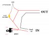
I am a guitarist who decided it would be nice to have a power switch for my custom-made pedalboard. I have a 9v AC/DC adapter rated at 1700 mA max that can power up to 8 pedals with 9v DC current. I thought it would be simple enough to build my own circuit, so I tried and failed. I cannot understand why. If it's not too much trouble, can someone attempt to troubleshoot this circuit?
 

Attachments

  • circuit.jpg
    circuit.jpg
    56.5 KB · Views: 183
That drawing shows that you've shorted out the resistor and LED. It also doesn't show where the other end of the battery goes or where the grounds end up.
 
Here's where my ineptitude will show... I thought what you call a "short" was an LED circuit wired in "parallel".

I should also be clear about the "IN" and "OUT" section... "IN" comes from the wall AC adapter, out goes to a 9V DC jack to feed the pedals. Thanks,

~Nate
 
OK. Now I've got it. That red wire in parallel with the resistor and LED is keeping the LED from working, but putting an LED in series with your pedal boxes is a foul idea, too. The way to do this is to run the 9V adapter through a switch to the pedal boxes and put the resistor and LED in series with each other, then attach that across the two wires carrying power to the pedals. I've done this before and found that different pedals sometimes have differenf grounds. As soon as you plug in a pedal with reversed ground, it shorts the whole thing. Put a fuse in so you don't smike the adapter if you meet a backwards grounded pedal, and know that if you do meet a backwards grounded pedal, you will need another 9V adapter.
 
I'm having trouble visualizing exactly what you're describing. What I do know is which pedals work with this system. I don't have many, and I check the box that the adapter came in to assure its polarity is compatible. You've been super helpful already, and I hate to ask for more, but is there any way you could draw up a quick schematic to be absolutely clear? Thanks,

~Nate
 
9V2pedals

This site requires me to type at least 10 characters or it won't upload.
 

Attachments

  • 9v2pedals.PDF
    206.3 KB · Views: 182
It works!! I can't thank you enough, this has inspired me to further my understanding of electronic circuits. Thank you, thank you, thank you!
 
Status
Not open for further replies.

New Articles From Microcontroller Tips

Back
Top