Hello guys! I need some helping building a circuit that works like this:
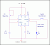
I have a button (the one that do not "lock" once you press it, but just goes back to the original position) and when you push it, a LED must turn on for 5-10 seconds (not a random value, but any fixed value from 5 to 10 seconds) and then it turns off.
-------------------------
<Push button>
<Led turn on>
<5-10 seconds>
<Led turn off>
-------------------------
Thanks a lot
Last edited: