Continue to Site

Welcome to our site!

Electro Tech is an online community (with over 170,000 members) who enjoy talking about and building electronic circuits, projects and gadgets. To participate you need to register. Registration is free. Click here to register now.

  • Welcome to our site! Electro Tech is an online community (with over 170,000 members) who enjoy talking about and building electronic circuits, projects and gadgets. To participate you need to register. Registration is free. Click here to register now.

Simple FM Transmitter - how does it work?

Status
Not open for further replies.

thunderbird

New Member
Hello everyone,

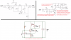
I've successfully built the Simple FM Transmitter from Makezine , which is based on Testsuo Kogawa's design.

However, I have no clue how this works? An internet and Google searched resulted in LC oscillators (tanks). Both of them clearly have a capacitor in parallel with the inductor (at the transistor's collector). It does looks like a Colpitts' oscillator in some modified way. However, I can't really figure out how the FM carriers is generated, and how the amplitude I guess (?) of the input wave is modifying the carriers' frequency (to result in FM?).

Can someone give me an explanation? I (think) I understand the transistor DC principle (that it needs to have fit DC conditions (like 0.7V BE voltage) to amplify the voltage swing at the base. There I'm afraid it stops and I'm eager to know more! :)

Thanks for any help and insight!

An electronic lover eager to learn more about those "analog" circuits! :D
 
I re-drew the schematic to show that C4 is actually in parallel with the inductor.
Then I pasted another very similar schematic of a transmitter with 4.7pF (almost nothing) between the collector and the emitter of the transistor.
Stray wiring capacitance easily creates only 4.7pF. Then the transistor is an RF common-base amplifier and the 4.7pF causes positive feedback from the collector to the emitter.

EDIT: The audio makes the transistor conduct more and less. Then the transistor's internal capacitance changes (see its datasheet to see how much) which modulates the oscillator frequency creating FM.
 

Attachments

  • FM transmitter.png
    FM transmitter.png
    96.1 KB · Views: 594
Hi audioguru,

Thank you very much for all the work you've put into the redrawn figure.

Can you explain me why C3 exactly causes the ground end of C4 to be also connected to the +9V. This was the part I didn't figure out when I tried to redraw the schematic myself. I just followed the 'lines' and noticed that the end of C4 is ground (not +9V). Of course I'm sure there is an explanation for that you'll get this C4 parallel to L1. Wondering :)

I understand the stray capacitance thing! :) And I should read more about positive feedback and also "grounding the base at the radio frequency". Some more reading should point me in the right direction for that. If I can't figure out the last two question, I"ll ask. But would be happy if you could explain the C4-magic ;-)

Thank you for your time!
 
A capacitor across the power supply causes high frequencies to see that capacitor as a short. So at RF frequencies the supply is a short.
On the right hand side the resonant current flows through L1 and C4.
On the left hand side the resonant current flows through L1, C4 and C3. (at RF C3 is a short)(C3 is 1000 times bigger than C4)
another way to say that:
On the right, C4=10pF,
On the left C4 looks like 9.99pF (almost 10pF). C3 in series with C4 looks like 9.99pF.
upload_2015-1-31_13-12-48.png
 
Did you look up "common-base amplifier"? The emitter is the input and the collector is the output. The stray capacitance from the collector to the emitter causes positive feedback. Any amplifier oscillates when it has positive feedback and some voltage gain that this transistor has.
 
There is a vital connection missing in AGs re-draw of this circuit:

Toy Transmitter.PNG


JimB
 
audioguru said-
The stray capacitance from the collector to the emitter causes positive feedback.

If audioguru's this sentence is true then a connection added by JimB is not needed, is it?

If stray capacitance between collector to emitter causes positive feedback and the positive feedback cause oscillation then why external capacitor from emitter to collector (like 4.7pf) needed?
 
Yes, of course. C5 plus some stray capacitance plus the capacitance of the transistor are used for positive feedback.
My simulations show that the output level is higher with less distortion when the value of C5 is increased from 4.7pf to 6.8pF.
This is the best I could make it perform:
 

Attachments

  • FM transmitter tweaked.png
    FM transmitter tweaked.png
    29.8 KB · Views: 243
Hi AG,

Feeling little confused, there's 47k in the base of OSC's transistor. Some OSC has 10k and some I found is less than 10k. However there's always 0.7V at bese, how? (yes, I know there's 0.7V comparatively to Emitter voltage) Does this BE junction creates this 0.7V? If yes then probably 10k conduction higher current level than 47k.

And there's no emitter resistor in RF amp but as a base resistor, I can use 47k or 33k or 100k too but always there's 0.7V at base, how?

I know it is very simple question related to basic Ohm's Law. I think there is very very tiny load which is 'base-emitter' impedance and due to the tiny load, voltage drop at base (which is 0.7V) is based on BE diode drop, instead of resistors's voltage drop. Am i right?
 
Last edited:
I know it is very simple question related to basic Ohm's Law. I think there is very very tiny load which is 'base-emitter' impedance and due to the tiny load, voltage drop at base (which is 0.7V) is based on BE diode drop, instead of resistors's voltage drop. Am i right?
yes.
 
The base bias resistor to the positive supply provides base-emitter current that turns on the transistor so it can do something. A transistor with a low current gain (beta or hFE) needs a lower value bias resistor than a transistor with a high current gain. The base draws current from the resistor and the base-emitter is a silicon diode with a voltage drop of about 0.7V. If the bias resistor value is low so the base current is high then the base-emitter voltage might be as high as 0.75V or if the base current is very low then the base-emitter voltage might be as low as 0.60V.

Selection of the base bias resistor value depends on the hFE of the transistor. Some transistors have a very wide range of hFE like a BC548 that is from 110 to 800. You can pay a little more for a BC548A, B or C which have their hFE tested and selected into a narrow range. I always use a 2N3904 little transistor that has its hFE in the range of 100 to 300 and calculate the base bias resistor for an average hFE of 200.

I selected capacitor values so that the output level is pretty high with low levels for the harmonics:
 

Attachments

  • FM good sinewave.png
    FM good sinewave.png
    29.6 KB · Views: 267
Did you look up "common-base amplifier"? The emitter is the input and the collector is the output. The stray capacitance from the collector to the emitter causes positive feedback. Any amplifier oscillates when it has positive feedback and some voltage gain that this transistor has.
I wasn't aware of this configuration. If I understand it correctly, the base of the transistor is common for RF signals due to C2 (capacitor at the base which is a short for high frequencies). The emitter is the INPUT while the collector is the OUTPUT. To keep the oscillations going from the tank circuit (formed by L1 and C4), it needs positive feedback. This feedback is provided by the stray capacitance (not shown on the schematic) between collector and emitter.

Some questions which do arise:

1) Does C5 (capacitor at the output) has other purposes than just providing AC-coupling to the (optional) antenna? If so, does it contribute to the collector-emitter stray capacitance? Is it correct that the it is not necessary to have the red wire drawn by JimB due to the stray capacitance?

1) Still figuring out how oscillation frequency is modified? I think there are two things to this:
(a) the common-base amplifier amplifies amplitude (I've read), it almost doesn't amplify current. So I think by coupling in the audio AC voltage, the magnitude of amplification is modified? Can I call this "the gain"?
(b) Still wonder how the FM is modified by the input voltage. I guess it has something to do with the some junction capacitance of the transistor varying by some voltage (hence act like some varcap)???

Well, this is a very interesting exploration for me into transistor amplifiers and FM modulation :) Thank you all so far!
 
To keep the oscillations going from the tank circuit (formed by L1 and C4), it needs positive feedback. This feedback is provided by the stray capacitance (not shown on the schematic) between collector and emitter.
1) Does C5 (capacitor at the output) has other purposes than just providing AC-coupling to the (optional) antenna? If so, does it contribute to the collector-emitter stray capacitance? Is it correct that the it is not necessary to have the red wire drawn by JimB due to the stray capacitance?
See post #6, I redrew it wrong. C5 parallel with stray capacitance and capacitance insde the transistor provide positive feedback. The antenna is connected directly to the emitter which is the output.

1) Still figuring out how oscillation frequency is modified? I think there are two things to this:
(a) the common-base amplifier amplifies amplitude (I've read), it almost doesn't amplify current. So I think by coupling in the audio AC voltage, the magnitude of amplification is modified? Can I call this "the gain"?
(b) Still wonder how the FM is modified by the input voltage. I guess it has something to do with the some junction capacitance of the transistor varying by some voltage (hence act like some varcap)???
Audio causes the transistor to conduct more which reduces its Vce and conduct less which increases its Vce.
Then the C-E junction of the transistor acts like a varicap and the amount the capacitance change with C-E voltage change is shown on the transistor's datasheet.

Many theory discussions show this circuit with another capacitor parallel with the emitter resistor. Then the oscillator looks more like a Colpitts oscillator.
 
Status
Not open for further replies.

New Articles From Microcontroller Tips

Back
Top