Hi,
I'm currently trying to repair and better (ideally) a subwoofer, as you will probably have seen from my numerous posts at the moment. I have a simple, practical question, that people might have experience with...
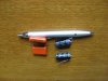
I'm trying to fit an improved capacitor, considerably larger that the previous on, on a PCB. The problem is not volume as such, as I am going to stick if underneath the PCB, but leads length! The PCB holes are close, between 0.5-1cm, where as the new caps I got are much wider, and the pins are not long enough to be brought inwards and connected. (See pic, hopefully attached correctly, the problematic caps are the orange ones to the left.)
In simple terms, how I get around this problem, ideally lengthening the those connectors, without it being much of a shabby DIY job...? I was originally thinking of soldering "extensions", but that would most likely result in nothing else but frustration and finger burns...
Thanks for the ideas!
I'm currently trying to repair and better (ideally) a subwoofer, as you will probably have seen from my numerous posts at the moment. I have a simple, practical question, that people might have experience with...
I'm trying to fit an improved capacitor, considerably larger that the previous on, on a PCB. The problem is not volume as such, as I am going to stick if underneath the PCB, but leads length! The PCB holes are close, between 0.5-1cm, where as the new caps I got are much wider, and the pins are not long enough to be brought inwards and connected. (See pic, hopefully attached correctly, the problematic caps are the orange ones to the left.)
In simple terms, how I get around this problem, ideally lengthening the those connectors, without it being much of a shabby DIY job...? I was originally thinking of soldering "extensions", but that would most likely result in nothing else but frustration and finger burns...
Thanks for the ideas!
")
