Electro Tech is an online community (with over 170,000 members) who enjoy talking about and building electronic circuits, projects and gadgets. To participate you need to register. Registration is free. Click here to register now.
Welcome to our site! Electro Tech is an online community (with over 170,000 members) who enjoy talking about and building electronic circuits, projects and gadgets. To participate you need to register. Registration is free. Click here to register now.
have tried 1R and 2R2 (only ones I have handy, they aren't high rated 1/2W but I'm not trying to load them up just getting the voltage right) I had checked the pin out its AOI looking front on. Very strange issue hey.
Also What MOSFET do you recommend for switching Positive current from a negative trigger?
Mike, Nevermind I re did the circuit again, turns out I had the 100R resistor on the pre 2 ohm GND. Circuit is working now. Although it seems to top out at 13.7ishV with the 5k pot. Thanks man!
So any suggestions on a FET or Transistor that can switch positive from a negative "gate" I really need to isolate the positive instead of negative. Cheers
Are you asking how to do a "high-side-switch" that switches say 15V to the positive pole of a battery that is controlled by a 5V PIC Port? If so, I posted that early in this thread.
What type of Transistor is the 2N3904? Is that just a standard ish NPN unit or a special one? and what type of FET is the IRF7406? Just trying to source a local similar unit. Would this **broken link removed** work? Thanks mate! Also I am pretty sure that my pic (12F675) is outputting 2v when high instead of 5v is there a program adjustment I can do to make it 5v or should the resistor be changed to something lower to trigger the transistor?
Thanks for your help mate! I might even be able to build a working prototype soon
NPN is garden variety
High-side switch is a PFET with its source connected to the positive voltage source, drain connected to battery!
What Vdd supply is the PIC running from?
A PIC port can only source ~20mA, so what load do you have connected to the Port?
Hey mike, thanks for your help and bearing with me and my silly questions
One other one, with all of this testing and playing around with the batteries, I have one more question to ask
Why couldn't I just use a LM317 or whatever regulator to get a fixed 13.8 or 14v voltage and simply put a 2.7Ohm (1w or 5w or similar) resistor or something in line with the battery to limit the maximum charge rate when it needs charging? Considering it will be on float (either without the resistor or with a very low resistance one for protection) whenever it is actually in use and the "charge" mode is only in rare situations when the battery is actually drained in any way (which would really only be caused by time based depletion if in an almost completely unlikely scenario when the 240v power isn't plugged in for a loooong time)?
The configuration that I am using this for, as you know Mike from my other project thread, is that it is picking up the slack for the SMPS and will remain on float power/charge whenever it is in use, as if there is no SMPS power the battery is not being touched.
So just a quick question. I've built a LM317 charger based on **broken link removed** circuit using a 1.5 Ohm 5W resistor in place of the "see text" the idea being to achieve a peak charge current of 0.39A or less and after some testing on a battery running about 12v and the voltage of the charger set to 14v or similar it was pushing 0.6A out to the battery which is beyond the rate the battery can sustain... its a 1.3Ah battery.
Any ideas? I calculated the resistor value based on that article.
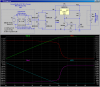
Note how this all comes together in the LTSpice sim, where I'm using a 2N3904 as Q1 and a 2.2Ω resistor as R5. Note V(EE), which is essentially the Vbe of Q1. Note that while Q1 is turned on by the drop across R5, its collector current Ic(Q1) is stealing current from the ADJ terminal of the LM317
Not sure how I buggared that simple equation up. Thanks for that mike.
Strange thing tho, I've changed out the resistor and installed a 2N3904 (I had a BC549 in there ) and set to 14v then applied to a battery that is at 12.5 (not flat but not full) and it initially put 1.2A out then settled at 700mA which is still far too high for the battery on hand. Any ideas why this is happening? the schematic is exact as per your diagram there asside from the input circuit, I have a 19v DC input to the LM317.
Notice that there is only one ground in the circuit. The neg end of the battery is the circuit ground. The neg end of the rectifer/filter cap (labeled EE in my schematic) must be allowed to go below ground by about 0.6V. It seems that you somehow have a short across R5.
This site uses cookies to help personalise content, tailor your experience and to keep you logged in if you register.
By continuing to use this site, you are consenting to our use of cookies.

")