Continue to Site

Welcome to our site!

Electro Tech is an online community (with over 170,000 members) who enjoy talking about and building electronic circuits, projects and gadgets. To participate you need to register. Registration is free. Click here to register now.

  • Welcome to our site! Electro Tech is an online community (with over 170,000 members) who enjoy talking about and building electronic circuits, projects and gadgets. To participate you need to register. Registration is free. Click here to register now.

Simple crystal oscillator circuit

Status
Not open for further replies.
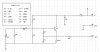
I have a 32 kHz crystal that I want to use as a clock pulse source. I have tried searching the net for oscillator circuits and have found some, but haven't had any luck simulating them.

Can someone tell me, in the simplest way possible, how to reliably make my crystal oscillate? I want to use in a clock and the O/P will go straight into a frequency divider then a counter. I want to ideally run it from a 9v battery, or two (depending on the overall current pull of the system).

Any help would be appreciated.
 
Crystal oscillators can take a long time (thousands of cycles) to start, due to the high "Q" of the crystal. In addition, oscillators sometimes need a kick to get them started in simulation (not necessary in hardware). Try adding an initial condition to one of the capacitors. If this doesn't work, you can add a one time PWL (100ua for 10usec) current pulse which is zero except for the duration of the pulse. This should work on almost any node in the circuit.
 
Thanks you for all the replies and help.

Ron, I tired your suggestion in my simulator and I still had problems. It seemed to stop after a cycle or two, and the whole thing would freeze up. This is a software problem, not a circuit problem I assume.

So, could anyone tell me if the circuit I have attached will oscillate my 32 kHz crystal? As you can probably tell I've had no experience with crystal oscillators before, so I'm kind of in the dark with all of this! Has anyone used this circuit, or had any experience with it?

Anymore advice or suggestions will be equally appreciated.
 

Attachments

  • xtal.jpg
    xtal.jpg
    37.6 KB · Views: 2,280
Can you post the subcircuit or the parameters for your crystal? I think I can help you. I got a sim to run (with some changes), but I need to have the crystal model you are using.
 
Ron,

Unfortunately, I have no idea what the crystals sub circuit is! As I said previously, I am new to XTAL oscillators. I was planning to work it all out for myself and teach myself the basics of them, but without any luck.

The crystals that I have (10 from eBay), have KDSIL down the side, and nothing else. I won them months ago on eBay, so the auction page is no longer viewable, so I can't get you any more information! All I know, well assume, is that they are 32 kHz. They are in metal cans which are about 8mm in length and 3mm in diameter.

Can I ask how you got the simulation to run, and what software you are using? Thank you for the help so far though, and sorry I can't provide you with more information.
 
I'm using Linear Technology's SwitcherCAD III, a totally free, no restrictions version of Spice.
What are you using? You should be able to view the netlist after simulation. The subcircuit for X1 will have the crystal model. If you can copy and paste it here, it would allow me to help you get your sim running. I'll post a schematic here if I do.

I got a 32kHz xtal oscillator to sim by cobbling up a model for a crystal and changing some component values in your schematic. I could post it here, but my crystal model is undoubtedly different from yours.
 
Ron,

I'm using the Textbook version of Multisim 2001. It came free with a text book I needed for universtiy. It's pretty good, simulates most things, but it does have one very big draw back - it can be overwhelmed. I tried simulating a counter circuit with some logic and 3 counters. One and two by themselves worked great, but adding a third confused it and it all fell apart.

As for the crystal model, its virtual. It's the only one the simulation has, but I did find some details about it's subcircuit. Although I don't know how useful you will find it!

* EWB Version 4 - CRYSTAL Model
* LS= 0.00254648 CS= 9.9718e-014 RS= 6.4 CO= 2.868e-011
LS 1 3 0.00254648
CS 3 4 9.9718e-014
RS 4 2 6.4
CO 1 2 2.868e-011

I hope this helps you in some way. I will look into your SwitcherCAD, sounds quite good.
 
That crystal model you have is for a 10MHz crystal.

Fc~1/(2*pi*sqrt(Ls*Cs))

The attached circuit oscillates for me on SwitcherCAD III. You have to let it run for about a second to get full amplitude. The crystal model is an educated guess, so you may get different results if you build it in hardware.
The output swings from a little below GND almost to VCC. It should drive CMOS logic OK, but you might want to improve the rise and fall times by running it into a Schmitt trigger. If you want to use TTL, we need to talk. :)
 

Attachments

  • 32khz_osc.gif
    32khz_osc.gif
    10 KB · Views: 1,460
Status
Not open for further replies.

Latest threads

Back
Top