So I have a gear set that sends a 5v trigger when it hits a detent, (normally at 0v). My new reader needs to see it as 5v and trigger to 0v. So it is basically a inverted output. This looks pretty close, but I cannot find this and not sure it is exactly what I am wanting. https://www.linear.com/product/LTC1261L
I attached what I think is my goal. If there is a simple 8-DIP IC I can buy and add a few resistors/capacitors, I am ll over this.
Stu
I attached what I think is my goal. If there is a simple 8-DIP IC I can buy and add a few resistors/capacitors, I am ll over this.
Stu
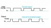
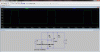
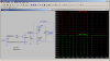
 ? A suitable comparator is the LM311 (8 pin IC). And attached is a circuit simulation screen-dump from LTSpice using a Linear Tech comparator, the LT1017. You can use the same value resistors for the LM311 (the values are not critical, but try keeping R1 = R2). The simulation waveform is on the top of the uploaded image. The Blue waveform is the voltage source V2, the green is the output from the comparator.