Electro Tech is an online community (with over 170,000 members) who enjoy talking about and building electronic circuits, projects and gadgets. To participate you need to register. Registration is free. Click here to register now.
Welcome to our site! Electro Tech is an online community (with over 170,000 members) who enjoy talking about and building electronic circuits, projects and gadgets. To participate you need to register. Registration is free. Click here to register now.
As I recall a BP(band pass)filter consists of a low pass filter and I high pass filter.
I think R4,C3 and R6,C4 is the high pass. I am not sure what the low pass components are.
I also recall that for both the filters the -3db point is where the reactance of the resistor and the capacitor is equal. So choose the 3db frequency, choose a resistor, then calculate the capacitor using the reactance formula.
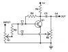
The Bandpass Frequency can be Changed to almost anything in the audio range.
This Circuit works fine and I can easily put in various caps and measure the BP Frequency. But it would be nice to have a Formula for it.
I Can't seem to come up with one that works.
In this Circuit, C1, C2 and C3 are All Equil in Value.
Typical Values range from about 500 pF to .2 uF.
The Pot is set to a point Just Below Self Oscillation, With No Input Signal.
This site uses cookies to help personalise content, tailor your experience and to keep you logged in if you register.
By continuing to use this site, you are consenting to our use of cookies.