Continue to Site

Welcome to our site!

Electro Tech is an online community (with over 170,000 members) who enjoy talking about and building electronic circuits, projects and gadgets. To participate you need to register. Registration is free. Click here to register now.

  • Welcome to our site! Electro Tech is an online community (with over 170,000 members) who enjoy talking about and building electronic circuits, projects and gadgets. To participate you need to register. Registration is free. Click here to register now.

Simple af amplifier function

Status
Not open for further replies.

den15betts

New Member
Hi guys this is my first post - please be gentle! My interest in electronics has just been piqued by my building a guitar effects pedal - a simple amplifier to boost the signal without (much) distortion.

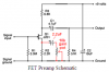
I was interested in how this thing worked so I hunted down and have (mostly) read 'Success in Electronics' - a book from my school days 25 years ago, which has a couple of chapters on audio freq. amplifiers. I understand how most of the pedal works but I don't understand the design of the circuit biasing the base - i.e. the 'cross' of the 100K, 10k, 47k resistors and 22µF cap.

My simple mind just can't come to terms with voltages, currents etc in this arrangment. Can anyone explain the choices made by the designer? I wish I'd paid more attention in physics lessons with Dr Newly nearly 3 decades ago (mind you he was a right git!).;)
 

Attachments

  • schem.gif
    schem.gif
    2.6 KB · Views: 350
That's a negative feedback circuit. The 100k and 47 k set the DC bias point, the 22uf cap and the 10k resistor provide AC (signal) feedback from the emitter resistor to control the gain. Gain in transistors wasn't well controlled in the early days, still isn't very precise. By balancing the DC bias against the current through the emitter resistor, you could get output biasing that was less dependant on beta. In the same way, by balancing that feedback cap against the emitter cap, you could control the AC gain independant of (but always less than) beta.
 
Last edited:
Bit of a confusing answer - it's actually a bootstrap circuit, used to give a higher input impedance, although setting the gain to maximum will totally destroy that function.

It's really a pretty poor circuit, trying to be a bootstrapped common collector, and a common emitter at the same time.
 
You're right, put a crystal on the base and it's a Colpitts oscillator. I need to take a moment before jumping in with an explanation sometimes.
 
As Duffy says, transistor gain goes all over the place, however it wasn't just in their earlier days. Even modern transistors may be specified with a beta or hfe of 100 - 200 as an example. That's why good circuit design have component values selected such that it's the external passive components that set the circuit gain and other parameters and not the transistor itself. That way, if you have to replace a defective transistor in a circuit, you won't screw things up all over the place and have to recalibrate or align things all over again.

Dean
 
A guitar pickup needs a very high load impedance. Usually a vacuum tube or FET transistor is used as a preamp. A transistor as an emitter-follower can be used if it is bootstrapped. Then a gain stage can be added.

This stupid circuit is trying to use a single transistor to do two things (bootstrapped input for a high input impedance and gain) then each thing is done poorly.
 
Wow - thanks guys. One thing is for sure: I have a lot to learn - I didn't understand a lot of what you've said but I really appreciate your time and expertise.

I don't know why this circuit is "stupid" but I do know that it works very well. I made it for about £25 (including DPDT footswitch and aluminium enclosure) - half of what a production pedal would have cost and it performs sooooooo much better than any of these.

I beleive the designer put it together as a project for begineers - it was my first soldering job and I'm pleased that it turned out so well. I'm quite disappointed to find that it's considered 'stupid'!!:p

thanks again, chaps.
 
The circuit is "stupid" because it combines the functions of two transistors but uses only one transistor.

As Nigel said, if the gain control is turned up to max then the bootstrapping does not work anymore and the circuit attenuates the signal because then its input impedance is too low.

The first transistor is supposed to be a bootstrapped emitter-follower with a very high input impedance.
The second transistor is supposed to have variable gain.
 
Thanks again.

Thanks - I'll have a go at breadboarding this tonight. How would I easily alter the gain - stick a variable cap in parallel with the source resistor?

I like this forum!:)
 
Last edited:
How would I easily alter the gain - stick a variable cap in parallel with the source resistor?
A variable cap in parallel with the source resistor would peak high radio frequencies and would have no effect on audio frequencies.
The text for the preamp says that you don't want more gain.

If something is wrong with your guitar that reduces its level then adding a capacitor in series with a 10k gain control pot and in parllel with the source resistor will allow the gain to be adjusted.
 

Attachments

  • guitar preamp with gain control.PNG
    guitar preamp with gain control.PNG
    7.3 KB · Views: 208
I wouldn't say it's stupid because it allows one transistor to do the job of two transistors, I'd say that's pretty clever.

I agree though that whilst it may have been useful back in the early 60s when transistors were expensive, it's not worth it today now transistors are cheap.

So it cose you £25 to build this circuit?

Where did you buy your components from?

What a rip-off! I couldn't imagine spending that much on such a simple circuit even if I bought the components from Maplin.

Those foot switches get pretty pricey.
 
I wouldn't say it's 'clever', because it doesn't allow one transistor to do the job of two - it 'attempts' to do that and fails.
Maybe it is a "clever" circuit after all:
1) With the pot set for minimum gain then the transistor has its input boostrapped for a high input impedance which allows the guitar pickup to produce a high output level which is not amplified by the transistor.
2) With the pot set for maximum gain then the input impedance of the transistor is very low which loads down the output of the guitar pickup to produce a low output level which is amplified by the transistor.
3) No matter what is the setting of the gain pot then the output level is the same.
4) The gain pot is really just a fuzz (distortion) control.
 
Last edited:
Status
Not open for further replies.

Latest threads

New Articles From Microcontroller Tips

Back
Top