Electro Tech is an online community (with over 170,000 members) who enjoy talking about and building electronic circuits, projects and gadgets. To participate you need to register. Registration is free. Click here to register now.
Welcome to our site! Electro Tech is an online community (with over 170,000 members) who enjoy talking about and building electronic circuits, projects and gadgets. To participate you need to register. Registration is free. Click here to register now.
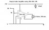
The TDA7052 is spec'd for 1W at 10% distortion (sounds very bad) into 8 ohms with a 6V supply.
With a 9V supply it should give an output of 2W at clipping.
But when its output is 2W then the poor little thing will get too hot.
Distortion figures of TDA7052 is same or better than all other amps on the category. Device is designed for typical 6-9V supply without need of any heat sink.
Advantages:
1. No external components.
2. Excellent stability.
3. Low power consumption and high output power.
4. Great Supply Ripple Rejection (50db).
5. Low output noise voltage.
A great performer for portable applications and can be assembled within minutes.
Use a digital log pot for dc controlled volume and mute and doesn't have a one click mute function I think. 7052A is used normally in TV sets with remote controlled volume.
7052 family is running successfully over 15 years.
The TDA7052A has a built-in DC volume control at pin4 that has a wide range of attenuation. Gain is +35.5dB if pin4 is +1.4V or more and is -44dB if pin 4 is +0.5V. The sound is muted (gain= -71dB) when pin 4 is +0.4V or less.
It is all on the datasheet.
The datasheet even has a schematic of a DC volume control and a 0.88W amplifier that can be reduced to 0.5W if the 6V power supply voltage is reduced a little.
You can't design an active filter unless you have details about it.
Ok, so I bought a 7052 and built this curcuit. I have disconnected the wires that went to my speaker, 8ohm, 0.5W. Which wire needs to go to the amp input? Where would my other wire go? Ground?
Thanks.
Ok, so I bought a 7052 and built this curcuit. I have disconnected the wires that went to my speaker, 8ohm, 0.5W. Which wire needs to go to the amp input? Where would my other wire go? Ground?
Thanks.
Sorry, I'm not being very clear. I am trying to boost the output of a phone answering machine. I disconnected the wires that went to the speaker. I am wondering which of these two wires need to go to the amp circuit input and would the other wire go to ground?
A TDA7052 power amplifier has almost the same low output power as the amplifier in an answering machine. You might not notice any difference.
The TDA7052 has a voltage gain of almost 100 so it will be severely overdriven unless the input is attenuated.
If the TDA7052 has a separate power supply from the answering machine then it might not make any difference which wire is signal and which wire is ground.
But the output of the answering machine might not work without an 8 ohm load.
using aattenuater for line out level can help you out. one wire should come from amp output electrolitic cap that should connect to 7052 in. other wire is ground. **broken link removed**
Ok, I'm really confused. With the circuit connected as I described, all i get is a loud buzzzzz. What exactly is an attenuator for? If the answering machine won't work without the 8ohm load, does anyone have a suggestion on how i can boost the volume up?
This site uses cookies to help personalise content, tailor your experience and to keep you logged in if you register.
By continuing to use this site, you are consenting to our use of cookies.

")