Continue to Site

Welcome to our site!

Electro Tech is an online community (with over 170,000 members) who enjoy talking about and building electronic circuits, projects and gadgets. To participate you need to register. Registration is free. Click here to register now.

  • Welcome to our site! Electro Tech is an online community (with over 170,000 members) who enjoy talking about and building electronic circuits, projects and gadgets. To participate you need to register. Registration is free. Click here to register now.

Silly newbie scope testing simple circuit question...

Status
Not open for further replies.

Molasar

New Member
Hello,

I have a silly question:

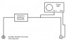
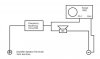
How would I go about connecting a scope (with a mega-ohm resistance) to check the tone frequency altered by the Frequency Modifying Circuit in the diagram WITHOUT disconnecting or breaking the circuit?

For the sake of simplicity, imagine that the freq-mod circuit will not work if the scope is placed in series after it.

Please advise! Remember... the circuit must not be broken.

The speaker may or may not even exist in the circuit. It makes no difference.

Is this possible?

Thanks!

Mike
 

Attachments

  • Freq Circuit.jpg
    Freq Circuit.jpg
    10.8 KB · Views: 151
Last edited:
To see the input, put the probe tip to the connection just before the modifier, and the ground clip to ground. To see the output, put the probe tip at the connection just after the modifier, or before the speaker (same net) with the ground clip to ground.

You don't place scopes in series. They are voltage measurement devices, not current.
 
Thanks for the quick reply, but I still have a question:

Wouldn't the current flow straight (after the modifer) thru the wire (0 ohm - imagine there is no speaker there) o even thru the speaker -8 ohm, instead of through the mega-ohm scope? Doesn't current flow through the least resistance path? Why would the current flow through the wire (and speaker) AND also through the scope (to get a reading)? This confuses me...
 
Last edited:
Current flows through every path it can find, not JUST the least resistance. The old adage of least resistance is a bit of a misnomer.

With a fixed voltage, current flows in direct proportion to the resistance (or impedance in case of AC) of each circuit it is supplying.
 
Last edited:
Thanks again!

That clears it up...

Last question:

If my amp does not have a three prong plug (so that the chassis is not grounded, or is made out of plastic, say)... would it be correct to place the scope's ground terminal to the negative speaker terminal?

Please excuse the dumb questions... I'm a total newbie.

Cheers!
 
Last edited:
Do not confuse Earth ground (the third round terminal on a plug) with circuit ground. They are COMPLETELY different things.

Circuit ground is just a reference point in the circuit that all other voltages are based on. Usually the negative rail of the power supply is used as ground, but not always. If your power supply outputs both positive and negative voltages, then your ground would be in the middle (only way to get both positive and negative.)

Again, it's only a reference point in the circuit and has NOTHING to do with earth ground. Do not connect your scope probe to earth ground.
 
Last edited:
Is this correct or valid?

Would I get a reading connecting the scope like this?

Cheers...
 

Attachments

  • Scope 3.jpg
    Scope 3.jpg
    13.6 KB · Views: 137
  • Scope 2.jpg
    Scope 2.jpg
    15.3 KB · Views: 140
You need the speaker in there to get a reading, otherwise both probes are basically touching the same wire, which will show you absolutely nothing. :)
 
Thanks...

So if the circuit does not include the speaker (which still makes for a valid circuit, because of the modifier's 8 ohm resistance.... seen by the amp as a valid load), is there a way to get a reading (without breaking the circuit - bear with me here)?
 
Last edited:
You seem to have a basic misunderstanding of a series circuit. If your "modifier" is some sort of frequency-dependent network that has only two terminals and is designed to operate when connected in series with a load like a speaker, then it makes no sense to remove the load and connect the only the "modifier" across the amplifier terminals. If you do, then the voltage across the modifier is the same voltage as are at the amplifier terminals (the independent variable); the current that flows through the modifier is some function of frequency(the dependent variable).

The usual way of measuring the current that flows is to introduce a small resistance (shunt) in series between the voltage source and the modifier network, and then use a voltmeter or scope to measure the voltage drop across the shunt. It would be better to just leave the load connected, and then measure the voltage across the load as a function of frequency...
 
Ok...

What you are saying is that the second diagram above (the one with the speaker) is the one that makes sense?

1. The scope in that diagram would show a reading?
2. If 1 is true, then can the speaker be replaced with an 8 ohm resistance and I would still get a reading?

I know it (question 2) might sound useless (why would anyone just modify the frequency output of an amp with no visible use?)...

What I'm trying to understand is how to "place" a scope in the circuit (without breaking it) and get a reading (in this particular scenario).

So I must understand that unless a load is present (speaker or resistance), the current (exiting the freq modifier) would just flow straight thru the circuit wire to the neg amp terminal and never (travel up the probe and) affect the scope? I only want a scope freq measurement; i.e.: I know I have a 1kHz tone at the amp terminals. I want to know the resulting frequency AFTER the freq modifier does its magic without interrupting the circuit or removing the freq modifier. Please bear with me here... I know there may be simpler methods...

Does this sound about right?


Thanks for bearing with me...
 
Last edited:
Lets start again from the beginning. :)

The basics of measuring any voltage in a system is by measuring the DROP of voltage ACROSS one or many components. See Kirchoff's law as to why.

As long as the voltages aren't going beyond your scopes capability (400V is what I see most on scopes, but check your own) then you can measure any two points in the circuit and get a voltage reading. What you are reading is the amount of voltage drop across that component.

In your case with the modifier and speaker, you want to see the difference in output between the input and output of the modifier. The speaker needs to be there so you have something to measure the output across. An 8-ohm resistor will also give you a reading, but it will be different from a speaker due to inductance. Speakers are rated 8-ohms of IMPEDANCE, which is resistance and inductance together. An 8-ohm resistor is measuring resistance only, since it doesn't have any inductance it's going to act somewhat different from the speaker.

Either way, you need something in your circuit to measure across; speaker or resistor. Put your grounding ring on one side of the speaker, and the probe tip on the other. Literallly measuring across the speaker. This is how you measure anything in a circuit. Nothing has to be broken to measure voltage. Just touch the two points with the probe.

Now, since you need to be able to compare the voltages you measure, you must make sure to use the same reference point in every measurement. You can literally pick anyplace in the circuit as your reference, however GND (most often the negative rail) is usually used to be consistent. Connect your ground clip to the battery/power supply negative rail, then use the probe tip to make all your other measurements. Now you have well referenced meaningful voltages.

Again, don't confuse circuit ground with earth ground. Completely different in this context.
 
Last edited:
Status
Not open for further replies.

Latest threads

Back
Top