Hello,
I'm getting some concepts confused.
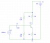
I'm building a 2 stage BJT amplifier, common emitter and emitter follower.
The behaivour of the circuit is quite accurate, as I measured values very near the ones I calculated on paper. The problem is the cutting frequency of the AC coupling capacitor at the input of first stage.
I use a 50 ohm signal generator, with a 1Mohm BNC scope probe to inject the AC component, trough a 100 nF capacitor. The stage input impedance is around 500 ohms.
The cutting frequency should be around 3 kHz, but the -3dB point, compared to max value attained at high frequency, is reached at 1.5KHz. It seems that the signal generator is not showing 50 ohm, but around 400 ohm, which forms a voltage divider with the input impedance (~500ohm) of the circuit.
Why? I tried to source a simple RC with a higher 2,2kohm and same 100 nF capacitor, and it corroborates it. The source is aorund 400 ohm output impedance, according to the voltage divider it makes.
Back to the bjt amplifier, at 3kHz, the theorical cutting frequency, the AC voltage in the base is -3dB the one present in the signal generator output (at the tip of the probe, to be exact). But NOT -3dB of the max value at higher frequencies, because the voltage on the tip of the generator's probe raises at frequencies near the cutting frequency, obviosly, because the capacitor impedance raises. So, the cutting frequency is the point at which the input is -3dB from the current voltage on the generator, but NOT -3dB from the maximun voltage at high frequencies. How can this be handled?
Thank you
I'm getting some concepts confused.
I'm building a 2 stage BJT amplifier, common emitter and emitter follower.
The behaivour of the circuit is quite accurate, as I measured values very near the ones I calculated on paper. The problem is the cutting frequency of the AC coupling capacitor at the input of first stage.
I use a 50 ohm signal generator, with a 1Mohm BNC scope probe to inject the AC component, trough a 100 nF capacitor. The stage input impedance is around 500 ohms.
The cutting frequency should be around 3 kHz, but the -3dB point, compared to max value attained at high frequency, is reached at 1.5KHz. It seems that the signal generator is not showing 50 ohm, but around 400 ohm, which forms a voltage divider with the input impedance (~500ohm) of the circuit.
Why? I tried to source a simple RC with a higher 2,2kohm and same 100 nF capacitor, and it corroborates it. The source is aorund 400 ohm output impedance, according to the voltage divider it makes.
Back to the bjt amplifier, at 3kHz, the theorical cutting frequency, the AC voltage in the base is -3dB the one present in the signal generator output (at the tip of the probe, to be exact). But NOT -3dB of the max value at higher frequencies, because the voltage on the tip of the generator's probe raises at frequencies near the cutting frequency, obviosly, because the capacitor impedance raises. So, the cutting frequency is the point at which the input is -3dB from the current voltage on the generator, but NOT -3dB from the maximun voltage at high frequencies. How can this be handled?
Thank you
")
