Electro Tech is an online community (with over 170,000 members) who enjoy talking about and building electronic circuits, projects and gadgets. To participate you need to register. Registration is free. Click here to register now.
Welcome to our site! Electro Tech is an online community (with over 170,000 members) who enjoy talking about and building electronic circuits, projects and gadgets. To participate you need to register. Registration is free. Click here to register now.
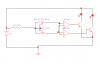
in this schematic i am controlling the outputs of the op-amps with the 2 pots, which is working fine, but i want to add a part that will detect when there is a change in the pots and switch another circuit on using a NpN. how would i do this?
That circuit does not seem to be designed correctly. I say this because its operation depends on the input current of the op amp.
Detecting change in an analog signal is not that simple, but a circuit that takes the derivative of the voltage could be used to generate a signal to turn a transistor on. That kind of circuit is called a "differentiator" and usually employs a capacitor to detect the change in voltage. If you need a schematic i can provide one. The idea would be to detect the voltage at the pot arms and generate a voltage according to how much they changed and how fast they changed.
Another way might be to use a comparitor with the arm of the pot to one side and the arm of the pot thru a resistor with a capacitor to ground on the other side. This would generate a pulse when the pot was moved. You would need one for each direction.
What is wrong with the configuration? All I am doing with the amp is detecting the difference in voltage, the pots are actually going to be photo sensors (Cd S)
what about if i put 2 caps in series between the pots, then between the caps i ran out a line through a diode to a smoothing cap and charge it to the transistor switch ?
Your circuit still isnt set up right, even without the capacitors. You'll need to use some resistors on the op amp inputs to ground perhaps. That will give the pots something solid to work into.
Do the pots have to be as high as 1 megohm or can they be lower value?
I just put the caps in as an AC detector, would that work? In my simulator the signal swings with the change in the pots but doesn't go back to 0v when idle, in reality it would though right?
my main concern is in fig 2 where I have my ac detector, would it work if i integrated it between the pots of figure 1?>? what can i add to capture that output signal and use it for switching?
......also in that first diagram i am using led's to represent the DC motor and i will be limiting the bases after i fig out which transistors ill be using, usually the 2n3055,
......also in that first diagram i am using led's to represent the DC motor and i will be limiting the bases after i fig out which transistors ill be using, usually the 2n3055,
hi D,
If I understand you correctly you want to detect when either of the two pots is adjusted.??
If so then it will only work when the percentage rotation of one pot exceeds the other due to adjustment.
example, suppose P1 is 50% and P2 is 60%,,, if you turn P1 to say 65% it would possible to detect a change, if you then moved P2 to 70% it would change back.
Is this what you want to happen.???
close, i want to close a latch when ...... either of the pots change over a second or ms or so ........
the op amp is wired to be light seeking schematic, so it detects the difference DC V and turns on the according motor,
so now the part i want to add in is a detector that will detect actual changes in the light sensors as oppose to the relation ship between them as in the op amp.
the pots are actually my photo-sensors, putting a voltmeter across them would measure V1-V2 , but i only want to measure dV1/dt and dV2/dt .....if that makes sense
a compactor.... but i don't need a amp , that's why i am thinking about 2 caps in series then tapping in between them for an ac signal then somehow smoothing it out to a switch with some hang time.
hi D,
If the two LDR's are matched in their light response, the circuit you have made with LDR's and the two fixed resistors form a bridge circuit.
So the comparator output should switch over when there is a difference in light falling on the two LDR's.
If the signal change from the LDR's is too small to use with capacitive coupling add amplifiers or you could consider using a cap coupling from the comparator outputs.
ya a differentiator i need , btw what is a comparator, thats when op amp is in normal configuration rite?
So how bout this config, the caps pull out my signal, transformer steps it up, but my rectifier doesn't keep the signal positive(my scope offset is at 1), maybe its just the simulator again?
In THEOrY i think it would look something like this next one when i'm done!? I am just hesitating to use another op-amp for this second part but maybe I may have no choice?
This way it should detect the transient step it up, rectify it, smooth it, and create a hold delay latch to power the mofet which powers the relay. Also i dont know much about mofets so that last part may not be wired properly, any suggestions?
This site uses cookies to help personalise content, tailor your experience and to keep you logged in if you register.
By continuing to use this site, you are consenting to our use of cookies.