Continue to Site

Welcome to our site!

Electro Tech is an online community (with over 170,000 members) who enjoy talking about and building electronic circuits, projects and gadgets. To participate you need to register. Registration is free. Click here to register now.

  • Welcome to our site! Electro Tech is an online community (with over 170,000 members) who enjoy talking about and building electronic circuits, projects and gadgets. To participate you need to register. Registration is free. Click here to register now.

Signal Detector for Robot

Status
Not open for further replies.

SPSU87

New Member
Hey everyone,

I'm building a circuit that is supposed to detect a wire that is carrying a certain frequency. when it is detected the robot needs to move away from the wire. I am using an LC circuit to pick up the wire and have it working.... partially. Here are my problems and questions.

When a large coil of the signal carrying wire come close to the LC circuit i get a clean signal on the o-scope but if only one strand of the wire is held near the LC then I get basically nothing. I tried putting the LC into a non-inverting op-amp and I am not getting any signal out of the op-amp. If I hard wire the signal generator into the op-amp I get a clean signal.

So it seems that for some reason the signal is not being carried from the LC circuit through the op-amp when trying to pick up the signal through the LC circuit.

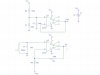
does anyone have any suggestions or advice on what I may be doing wrong. I can provide a schematic of what I have hooked up so far if it will help.


Thanks in advance for any help.

~mike
 
Yes, provide a schematic. Sounds like you don't have the gain set high enough, or it's tuned wrong or something.
 
Here is the way I have the receiving circuit hooked up. The signal is coming from a wire and I am picking it up with the Inductor/capacitor.

I have tried several different gain ratio all the way up to 1000x gain... which I'm sure isn't a good idea to do all in the same op amp.

When I probe just the LC i can get the desired signal and it has about 4mV p-p with the entire coil of wire near the inductor. The problem is the inductor will only be in contact with part of the wire at any time.

I hope this clears up my question. If no let me know.

Thanks for your help! It is VERY appreciated.

~mike
 

Attachments

  • Amp Sch.jpg
    Amp Sch.jpg
    55 KB · Views: 340
I have been told that an antenna wont work because the wire carrying the transmitting signal is working on the magnetic field and antennas work on the electric field.

The inductor/capacitor circuit is working and I'm getting a signal but the signal is weak when only a portion of the wire is near the inductor. I would think that it just needs to be amplified several times to get a good signal.
 
That circuit might actually work in a crude manner. Did you try putting an antenna on it?

No it won't, the non-inverting input is shorted to the -ve rail via the coil.

He should use AC coupling, and bias the non-inverting input at half the supply rail (and throw the extra opamp away).

10x gain is also pretty low, and the 741 is a useless old opamp, use higher gain and something like a TL081.
 
Nigel's right, connect that coil to Vcc2 instead of ground. And get a better amp - the 741 is crap with a single +5V supply, you only get a couple of volts of swing. Look for a rail-to-rail amp.

But the second opamp isn't useless, it's serving as a rail splitter. That's fine - leave it.

And, like I suspected, your gain is too low. Make R8 1k, or better yet put a pot in there.
 
Last edited:
Could you explain what you mean by AC coupling please. How would I bias the non-inverting input at half Vcc with out the first op-amp? I will try the TL081 as I too have heard that the 741 is useless. It is just what I have used fro school.
 
It doesn't need an AC coupling cap. Reconnect the coil like I said. Leave the other amp alone.
 
Duffy,

So what you are saying is to remove the cap "C7" in my schematic? Wouldn't that take away the filtering that the parallel LC is doing? Or am i understanding you wrong...
 
No, not C7. That's part of the tank circuit. Nigel was talking about something else with an extra cap.

First reconnect L1 and C7 from that ground to Vcc2 instead. Big improvement right there. Next, increase the gain by reducing R8. More improvement. At this point, come back so we can make fun of you for using an old 741 opamp again, and then tell us how close you are to where you need to be.
 
Last edited:
Thanks a bunch for the help. I will give that a shot tomorrow and let you know how it goes.

THANKS AGAIN!
 
IT WORKS!!!!!! Thanks SO MUCH for ya'lls help. I knew it was something with how the LC was connected to the op-amp i just needed a kick in the a@@ to figure it out.

The signal is still to small to use so I tried to add another gain stage of 100x but for some reason the waveform went strange on me. It's like its picking up a new signal?

I just connected the output from stage one to the non-inverting input of stage two and connected everything else like the stage one op-amp. Am I missing something here?

Again thanks for the fast responses and help!

~Mike
 
Just reduce R8 and increase R9 if you need more gain. The 741 isn't great, but the gain is in the tens of thousands - enough for an inductive loop detector.

Peak-to-peak is only going to be a couple of volts, though the 741 can't go rail-to-rail; it stops a couple of volts short of Vcc and Ground. Can you increase Vcc to 9V or 12V? You should see better results with that arrangement.

At some point, redo the circuit using an LM6132 amp. Different pinout, but much better specs. The output goes rail-to-rail, so you get the full 0 to 5V. Better gain, better impedance, and frequency response.
 
Don't you start increasing the risk of a noisy output by trying to make the gain on a single stage too high? That's why I was trying a second stage instead of trying to get all the gain out of the one. I am going to buy a TL082 at Radioshack tomorrow and try it instead of the 741 now that I know the circuit fundamentally works.
 
Not with this circuit. Opamps are designed for high gains, they are multi-stage and compensated internally by miraculous elves working magical charm into each and every slice of silicon goodness.

At least at these frequencies.
 
Status
Not open for further replies.

Latest threads

Back
Top