Electro Tech is an online community (with over 170,000 members) who enjoy talking about and building electronic circuits, projects and gadgets. To participate you need to register. Registration is free. Click here to register now.
Welcome to our site! Electro Tech is an online community (with over 170,000 members) who enjoy talking about and building electronic circuits, projects and gadgets. To participate you need to register. Registration is free. Click here to register now.
I have an IPOD NANO 5th Gen and a set of Lynx aircraft head phones which are monaural. If I short the left and right channels together so I can pipe it into the Lynx head phones, is there a risk to the IPOD?
Thanks,
Kinarfi
Most modern personal electronics, IPODs, CD/MP3 players, FM stereo radios, use IC audio amps that have an effective output impedance of << 0.1Ω. If you short the left channel to the right channel, the two amplifiers end up fighting each other, causing severe distortion, and drawing excessive current from the batteries, causing the batteries to go dead very quickly. Putting the bridging resistors externally is necessary!!!
Most modern personal electronics, IPODs, CD/MP3 players, FM stereo radios, use IC audio amps that have an effective output impedance of << 0.1Ω. If you short the left channel to the right channel, the two amplifiers end up fighting each other, causing severe distortion, and drawing excessive current from the batteries, causing the batteries to go dead very quickly. Putting the bridging resistors externally is necessary!!!
I'm fully aware of the output impedance of audio power amplifiers, but I'm also aware that it's normal practice to feed the headphone socket via current limiting resistors as well, which allows you (in almost all cases) to simply join them together, as the required resistors are already in place.
As I said, I can't comment on an iPod specifically, as I've never seen inside one - but any kind of decent design would use the resistors.
Battery-powered personal electronics devices that run on 3V batteries are designed to drive ear-buds or headphones with an impedance of ~30 Ohms as the normal load. Since the peak-to-peak amplitude of the audio is so constrained by the battery voltage, the last thing they want to do is to put a series resistor between the output of the amplifier and the earphone...
Battery-powered personal electronics devices that run on 3V batteries are designed to drive ear-buds or headphones with an impedance of ~30 Ohms as the normal load. Since the peak-to-peak amplitude of the audio is so constrained by the battery voltage, the last thing they want to do is to put a series resistor between the output of the amplifier and the earphone...
Thanks for the inputs, think I'll build a amp/isolator for my mono phones since they don't have a volume adjustment for input and one for voice, just the built in voice one.
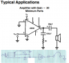
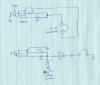
It'll be another fun project, probably a LM386N-4/NOPB from Allied Electronics, $1.00 each. Mike, it's 22 Ω from the right and 22 Ω from the left to amp input plus the common, correct?
Thanks Again, Don't want to mess up my new ipod.
Kinarfi
Your sketch does not show a volume control. Instead it shows a variable resistor to ground that shorts the input signals. A volume control does not short the input signal.
You should use an audio-taper pot of 10k to 20k for a volume control. Its slider connects to the input of the LM386 power amp.
Your sketch does not show a volume control. Instead it shows a variable resistor to ground that shorts the input signals. A volume control does not short the input signal.
Even with the pot set to zero ohms, the amplifiers in the IPod are protected because they see a 22 Ohm load. The LM386 likes a low source impedance. I'm guessing that for a comfortable listening level, the pot will be set near max resistance, and that the user will be using the volume control on the IPod, anyway...
btw-I've been using this exact circuit in my airplane for ~10years... works just fine.
Mike,
Got your circuit built and so far, it works great, turns out, the Ipod can be set to mono. Didn't need the level control, I can just turn the Ipod down if I need, the circuit has good volume and works great with my Lynx head phones. Used the minimum parts schematic from the Data sheet.
Here's where I use it,**broken link removed** See the head phones in the middle of the hood? They help keep the ears warm too.
Thanks Mike.
Kinarfi
FYI, here is what is happening: Note that each channel of the IPOD sees a load impedance of ~44Ω, which is not unlike the normal 35Ω earbuds. The output voltage is the sum of the two channels, attenuated by 2 (-6db). The two 22Ω resistors form a symmetrical voltage divider for each channel. The 50K input impedance of the LM386 has negligible effect on the voltage divider.
This site uses cookies to help personalise content, tailor your experience and to keep you logged in if you register.
By continuing to use this site, you are consenting to our use of cookies.

 but will work fine.