evandude
New Member
For an RFID project, I need to be able to selectively short an AC input signal to ground (this is to short the input coil terminals as well as possible, which is how the tag transmits data back to the reader)
I use the term "short" loosely here, as there will of course still be a voltage drop over the diode and transistors, however it's not significant compared to the amplitude of the input signal it is "shorting" (which has been 80-100Vpp in testing)
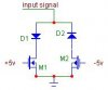
so far the best i've come up with is this. the diodes make it so each transistor shorts the input signal for half its cycle (positive or negative side)
it seems like a usable design, the only problem is that A) it doesn't seem very elegant, and B) it requires a negative rail for the PMOS gate.
I can have a negative power rail, but that's just about all it would be used for so if I could do this differently and eliminate it, that would be preferable.
I am looking into the use of triacs, as they seem like they could do what I need. Specifically, I'm looking at opto-triacs so I can drive them with a logic output... But I'm not familiar with triacs at all, so maybe you guys can shed some light on whether these would be of any use to me. I'm worried about the amount of current it takes for the output to "function", as the amount of current coming from this coil is going to be pretty weak (haven't quantified it yet though)
I use the term "short" loosely here, as there will of course still be a voltage drop over the diode and transistors, however it's not significant compared to the amplitude of the input signal it is "shorting" (which has been 80-100Vpp in testing)
so far the best i've come up with is this. the diodes make it so each transistor shorts the input signal for half its cycle (positive or negative side)
it seems like a usable design, the only problem is that A) it doesn't seem very elegant, and B) it requires a negative rail for the PMOS gate.
I can have a negative power rail, but that's just about all it would be used for so if I could do this differently and eliminate it, that would be preferable.
I am looking into the use of triacs, as they seem like they could do what I need. Specifically, I'm looking at opto-triacs so I can drive them with a logic output... But I'm not familiar with triacs at all, so maybe you guys can shed some light on whether these would be of any use to me. I'm worried about the amount of current it takes for the output to "function", as the amount of current coming from this coil is going to be pretty weak (haven't quantified it yet though)