Continue to Site

Welcome to our site!

Electro Tech is an online community (with over 170,000 members) who enjoy talking about and building electronic circuits, projects and gadgets. To participate you need to register. Registration is free. Click here to register now.

  • Welcome to our site! Electro Tech is an online community (with over 170,000 members) who enjoy talking about and building electronic circuits, projects and gadgets. To participate you need to register. Registration is free. Click here to register now.

Sharing same LCD between two microcontroller boards.

Status
Not open for further replies.

savvej

Member
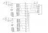
I have two microcontroller 8051(P89v51rd2) boards and have made an lcd board having two set of output pins available for each lcd pin.
LCD is given VCC,and Gnd separately. And the microcontroller boards have a separate power supply and power supply switch(with the grnds of each of the boards and the lcd unit connected together)
Two set of connector wires connect each of the pins rs,rw,en,d0-d7 to each of the two microcontroller ports.
The LCD is always powered on.
Now when I switch on one of the boards(say board1) while the other is powered off ,there is nothing displayed on the LCD.But if I now disconnect the LCD connector from board2(the other board) and then again restart board 1 ,it works perfectly fine.
Similarly if I switch on board 2 and remove LCD connector from board1,it too works fine.This implies that each of the unit works fine independently.
But when both connectors are connected with only one of them switched on it doesn't work.

So what I think is that sharing of LCD pins to the other microcontroller affects the voltage levels at the microcontroller LCD PORT ouyput even though the other is switched off (i.e. its pin40(VCC) is disconnected from power supply).What I have proposed is that can connecting low voltage drop diodes(like 1n4148) and the LCD port pins of microcontroller solve this problem by keeping the voltage levels fixed the individual ports?
Please comment and suggest some solutions for the same.
If you want any info regarding voltage levels at the pins or any other info please do ask.
 
Last edited:
hi,
You should not connect active outputs together, diodes will not solve your problem.
Even though the power is off in one of the 8051, it will 'sink' thru its internal diodes any external signal.
You require a data selector IC.
 
@ericgibbs

Even if I am diconnecting the entire power supply i.e. diconnecting VCC and Grnd ,then too it does'nt work(i.e. with the LCD connector connected to the two boards),then too it does'nt work.How do you explain this?

Could you suggest some data selector IC to be used in this case?
 
Even if I am diconnecting the entire power supply i.e. diconnecting VCC and Grnd ,then too it does'nt work(i.e. with the LCD connector connected to the two boards),then too it does'nt work.How do you explain this?

Could you suggest some data selector IC to be used in this case?

hi,
You need to consider what components are inside the unpowered IC.
Assume you made a small section of the internal circuitry on a project board and the board is not powered in anyway.
If you tried to measure the resistance between two points of your circuit with meter, the meter test voltage would find the least path of resistance thru your circuit, it would not necessarily measure open circuit.
The same applies to the 8051's one powered, one not.
If say one active pin [ an active pin is either set low or high] of the powered 8051 is connected to a pin on the non powered 8051, it could find a conductive path thru it to another pin.
Remember you are talking of a number of pins linked in this way.!

Are you using the RW pin on the LCD.?
 
Last edited:
@ericgibbs

But as I said I have disconnected both the VCC and the ground of the 8051.So when I connect the connector to it while it unpowered in this way,should'nt it have no path to complete circuitry ? Or s it that when 8051 s unpowered,the resistance between its port pins is low and could in turn cause the singal to get completely distorted at the LCD connector.
But When 8051 is powered,the resistance between its adjacent pins must be infinite (when its in floating state)?right?
Also could you suggest some popular data selector IC(byte data demultiplexer icright??)( (For connecting 2,8 bit outputs from microcontoller to LCD display output)
 
Last edited:
No. I have permanently grounded the RW pin.(*mistake while defining my problem.I have connected only rs,en,d4-d7 to connector to the microcontroller board)

hi,
Look at the HEF4053 IC, you would need two.
Note: you would have to reinitialise the LCD whenever you change the selection.

Can you say why you need to power down one IC and share an LCD.?
 

Attachments

  • HEF4053.pdf
    118.6 KB · Views: 382
But as I said I have disconnected both the VCC and the ground of the 8051.So when I connect the connector to it while it unpowered in this way,should'nt it have no path to complete circuitry ? Or s it that when 8051 s unpowered,the resistance between its port pins is low and could in turn cause the singal to get completely distorted at the LCD connector.
But When 8051 is powered,the resistance between its adjacent pins must be infinite (when its in floating state)?right?

That would be my assumption.
If you didnt have to power down the unused 8051, you could set the pins to all inputs.
 
So supossing that I remove LCD initialization from one 8051uC and keep only displays routine only on it,also keep its pins as all input,and switch on both the boards ,keeping the function of initialization in the other uC,will this solve my problem?
 
@3v0 & @erricgibbs

actually the 8051 boards are custom made(i.e. its PCB not development board where I can change connections).Only the LCD connectors are detachable from both the boards .So I can't make now one microcontroller sending request to other for display(because I have only 2 spare pins left on each of microcontroller).What I am planning is follows :
1)Change code and use one extra pin(name it command pin,set by default to high) from each of the boards .This pin will be used to indicate whether the uC is to be in "Halt" state or not.
2)Both the boards will now have a common power switch.
3)When powered on,each of them will be in a "Halt" state till it gets a signal on the "command pin".
3)And the other power switch will be replaced by a DPDT switch such that when its is switched UP ,board 1 gets command to now set its port as output and initialize LCD and continue its normal operation.
4)Now to select board 2,reset the power supply to both the boards,so that again they are in "halt" state and now when the switch is pushed DOWN,board2 will get command signal,board 1's LCD output will be put to high impedance and board2 will do its normal operation.

So do you think this strategy will work?(Also @ erricgibbs could you tell why would putting diodes in line from LCD connectors to LCD not work?If I removed both VCC and GRD from one board,and considering that the impedance between pins is low in off state,the didoes should work as they will block the path of signal from other board and its signal levels would be maintained?)
 
@bluerroom electronics

actually as I said the hardware is all ready,so I can't really do anything to fiddle with.
I am still amateur using microcontrollers ,and I agree that during designing the fault was mine.I should have divided the projects into modules like 1 or 2 uC for processing operations and they interfaced to a display dedicated uC wherein they communcate with each other using uart or something...
But now that I have told my problem,do you have alternative solution?
 
So do you think this strategy will work?(Also @ erricgibbs could you tell why would putting diodes in line from LCD connectors to LCD not work?If I removed both VCC and GRD from one board,and considering that the impedance between pins is low in off state,the didoes should work as they will block the path of signal from other board and its signal levels would be maintained?)
Which way around do you think the diodes should be in order set an LCD pin High or Low.???

As Bill suggests, post a diagram.
 
Last edited:
@3v0 & @erricgibbs

In the schematic I have attached ,the power pins for each of the uC is not shown and also I haven't shown the other peripherals attached to the ports of each uC.
So considering that I have separate power switches for each of the uC,will this arrangement solve my problem?
 

Attachments

  • board.JPG
    board.JPG
    74.8 KB · Views: 392
Status
Not open for further replies.

New Articles From Microcontroller Tips

Back
Top