Continue to Site

Welcome to our site!

Electro Tech is an online community (with over 170,000 members) who enjoy talking about and building electronic circuits, projects and gadgets. To participate you need to register. Registration is free. Click here to register now.

  • Welcome to our site! Electro Tech is an online community (with over 170,000 members) who enjoy talking about and building electronic circuits, projects and gadgets. To participate you need to register. Registration is free. Click here to register now.

Sharing MCLR between 2 PICs

Status
Not open for further replies.

Mark_R

Member
Hi,

I have 2 PICs (18F4620 & 16F684) and would like to share 1 reset button. I think my scheme will work, but was looking for opinions. See attached...

Explanation:
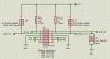
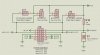
J10 is the programming port, the left is to program µC A, the right is for µC B.
For normal run, pins1&2 would be shorted to allow the reset and pullup to be shared.

J11/J13 are solder jumpers to provide power to their respective PICs that would be shorted for normal run, open to program using power from the programmer. J12/J14 are 2 pin headers with the same purpose, only populated for development work.

My concerns:
  1. OK to have both µC share one reset circuit with both MCLRs tied together?
  2. During programming, µC A would not have the benefit of the 10K pullup on MCLR as the jumper on J10 1&2 would be removed. Is it needed?

Thanks.
 

Attachments

  • ICSP.jpg
    ICSP.jpg
    84 KB · Views: 183
Last edited:
Hi,

You cannot leave a Mclre floating - it will cause all sorts of Reset problems.

Assuming you are using a Pickit2/3 programmer ? - you do not normally connect it directly to the pic and the Mclre 10k pull up, it must be 'isolated' - see the pickit2 Users Manual for how to add the extra components.

Think using two separate switches / circuits a better option, so many jumpers bound to lead to confusion - even when using more obvious switches you can still get things wrong.

edit - see this recent post /diagram https://www.electro-tech-online.com/threads/isolating-pgd-and-pgc.118383/

Hi,
Trying to avoid 2 reset buttons for the system.
The pin headers are for development only and would not be populated for normal production units. The PICs are socketed and would be normally programmed off board. The thought was that J11 & J13 would be solder bridged during board production, and J10 pins 1&2 would also be shorted with a cap tying both MCLRs to the 10K pullup. If MCLRs are high impedance, I would think this would be OK.

I'm using a Pikit3, I've seen conflicting diagrams showing the pullup resistor both in and out of the circuit during program, not sure which is correct. During programming with J10 pins 1&2 NOT shorted, µA woul;d not have the pullup, and µB would. That's the part that's sketchy for me.
 
Hi,

Most pcb switches are double pole so you can then effectivley have separate Reset circuits.

You do not say what each chips Mclre is being used for - As a Mclre / Reset pin or configured as an i/o pin ?
 
The more I ponder this, the more I believe the pullup is needed during programming as well. Perhaps I could use a 10K pullup on both MCLR lines. This would give 10K to each µC during programming, and 5K parallel resistance to both when J10 pins 1&2 are bridged for normal run. Both values being within the 4.7K-10K spec.
 
Hi,

Most pcb switches are double pole so you can then effectivley have separate Reset circuits.

You do not say what each chips Mclre is being used for - As a Mclre / Reset pin or configured as an i/o pin ?

Double pole switch would be ideal, and was my first thought, but most of the tact switches I found appear to internally parallel the poles. Couldn't seem to find a readily available DPST configuration. Pins are only for reset / ICSP, no I/O use.
 
Update-
Decided I really need the pullup on both PICs when the MCLRs are split for programming. I'm going with a 10K pullup on each MCLR, giving me 5K equivalent resistance when the jumper is in the circuit for normal run. The spec appears to be 4.7K to 10K so I'm good for both situations.

No confirmation yet that I can have the MCLR pins tied together sharing a common reset during normal run, but I can't see why not. Still bee nice to hear from someone who had done it before.

EDIT: I ran a renumber on the components but never updated the note on the schematic. The note on the bottom of the schematic should read J5, J6 & J7.
 

Attachments

  • ICSP.jpg
    ICSP.jpg
    61 KB · Views: 182
Last edited:
Status
Not open for further replies.

Latest threads

New Articles From Microcontroller Tips

Back
Top