Continue to Site

Welcome to our site!

Electro Tech is an online community (with over 170,000 members) who enjoy talking about and building electronic circuits, projects and gadgets. To participate you need to register. Registration is free. Click here to register now.

  • Welcome to our site! Electro Tech is an online community (with over 170,000 members) who enjoy talking about and building electronic circuits, projects and gadgets. To participate you need to register. Registration is free. Click here to register now.

Servo Motor with PIC16F877

Status
Not open for further replies.
I worked out a couple concepts awhile back from ideas proposed by another Forum member but they require an extra chip (a 74HC4017 Johnson ring counter or a 74HC238 decoder).

Both use the CCP module in "compare" mode to provide 8 rock solid hi-rez' no-jitter servo outputs with a 20-msec period. The 74HC4017 version could also provide 9 outputs with a 22-msec period.

Since the '877A has two CCP modules I suppose you could connect two 74HC4017 devices for 16 or 18 servo outputs but I have not worked out an algorithm or code to support that.

While the processing "overhead" for this scheme is incredibly light, I'd still consider off-loading Servo control to a little 12F683 / 74HC4017 board with crystal and simple serial interface and command structure.

I hope you don't mind the different idea. Good luck with your project.

Regards, Mike

Here's the ISR "engine" for the 74HC4017 version of the Servo controller;

Code:
        org     h'0004'

ISR_Vector
;
;  save main program context
;
        movwf   W_ISR           ; save W-reg                      |B?
        swapf   STATUS,W        ; doesn't change STATUS bits      |B?
        movwf   S_ISR           ; save STATUS reg                 |B?
        clrf    STATUS          ; force bank 0                    |B0
        movf    FSR,W           ;                                 |B0
        movwf   F_ISR           ; save FSR                        |B0
;
;  clear CCP1 interrupt flag and CCP1 "CLK" line
;
        bcf     PIR1,CCP1IF     ; clear CCP interrupt flag bit    |B0
        bcf     PORTB,CLK       ; clear CCP1/RB3 'CLK' pin        |B0
;
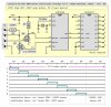
;  Qarray holds ten 16-bit period values, one for each of the
;  ten shift register Qn outputs.  Eight Qn outputs and periods
;  drive Servos.  The other two Qn outputs are unused but their
;  periods are used to complete a 20-msec Servo cycle.
;
;  Qarray(0) is Q1 Servo 1 "on" time, 400..2400
;  Qarray(1) is Q2 Servo 2 "on" time, 400..2400
;  Qarray(2) is Q3 Servo 3 "on" time, 400..2400
;  Qarray(3) is Q4 Servo 4 "on" time, 400..2400
;  Qarray(4) is Q5 Servo 5 "on" time, 400..2400
;  Qarray(5) is Q6 Servo 6 "on" time, 400..2400
;  Qarray(6) is Q7 Servo 7 "on" time, 400..2400
;  Qarray(7) is Q8 Servo 8 "on" time, 400..2400
;  Qarray(8) is Q9 unused cycle time, 400 (fixed)
;  Qarray(9) is Q0 end-of-cycle time, 400..16800
;
;  add current Qarray(Qn) period to previous CCPR1L:CCPR1H
;
        setc                    ; set carry                       |B0
        rlf     Qindex,W        ; Qn index [0..9] * 2 + 1         |B0
        addlw   Qarray          ; add to array base address       |B0
        movwf   FSR             ; setup indirect address          |B0
        movf    INDF,W          ; Qn period hi [400..2400]        |B0
        addwf   CCPR1H,f        ; set new CCP compare time hi     |B0
        decf    FSR,f           ;                                 |B0
        movf    INDF,W          ; Qn period lo [400..2400]        |B0
        addwf   CCPR1L,f        ; set new CCP compare time lo     |B0
        skpnc                   ; carry?  no, skip, else          |B0
        incf    CCPR1H,f        ;                                 |B0
;
;  subtract current Qarray(Qn) period from Q0 end-of-cycle time
;  in Qarray(9)
;
        movf    INDF,W          ; Qn on-time lo [400..2400]       |B0
        subwf   Qarray+.18,f    ; subtract from end-of-cycle lo   |B0
        incf    FSR,f           ;                                 |B0
        movf    INDF,W          ; Qn on-time hi [400..2400]       |B0
        skpc                    ; borrow? no, skip, else          |B0
        incfsz  INDF,W          ; increment subtrahend            |B0
        subwf   Qarray+.19,f    ; subtract from end-of-cycle hi   |B0
;
;  increment Qindex [0..9] for next Qn period
;
        incf    Qindex,f        ; increment Qn index              |B0
        movf    Qindex,W        ;                                 |B0
        xorlw   d'10'           ; end-of-cycle?                   |B0
        bnz     ISR_XIT         ; no, branch, else                |B0
;
;  reset Qindex and Q0 end-of-cycle time in Qarray(9)
;
        clrf    Qindex          ; reset Qn index to 0             |B0
        movlw   low  d'20000'   ; reset Q0 time to 20000 usecs    |B0
        movwf   Qarray+.18      ;                                 |B0
        movlw   high d'20000'   ;                                 |B0
        movwf   Qarray+.19      ;                                 |B0
        bsf     PORTA,CLR       ; force Q0 output sync            |B0
        bcf     PORTA,CLR       ;                                 |B0
;
;  restore main program context
;
ISR_XIT
        movf    F_ISR,W         ;                                 |B0
        movwf   FSR             ; restore FSR                     |B0
        swapf   S_ISR,W         ;                                 |B0
        movwf   STATUS          ; restore STATUS                  |B?
        swapf   W_ISR,f         ; don't screw up STATUS           |B?
        swapf   W_ISR,W         ; restore W-reg                   |B?
        retfie                  ; return from interrupt           |B?
Here's the same ISR "engine" in C18 code for an 18F' device;

Code:
/*****************************************************************
 *  ISR    (high)                                                *
 *****************************************************************/
#pragma interrupt isr_hi

void isr_hi ()
{
  if (PIR1bits.CCP1IF == 1)             // CCP1 interrupt?
  {
    PIR1bits.CCP1IF = 0;                // clear CCP1 interrupt flag
    LATCbits.LATC1  = 0;                // clear CCP1 "CLK" line

    CCPR1H += (Qarray[Qindex]/256);     // update "match" period value
    CCPR1L += (Qarray[Qindex]%256);     //  for this Qn period

    Qarray[9] -= Qarray[Qindex];        // adjust end-of-cycle time
    Qindex = Qindex++ % 10;             // increment Qindex [0..9]

    if (Qindex == 0)                    // end-of-cycle (0)?
    {
      Qarray[9] = 22000;                // reset end-of-cycle time
                                        // for 9 Servo periods and
      LATAbits.LATA0 = 1;               // force 74HC4017 Q0 sync'
      LATAbits.LATA0 = 0;
    }
  }
}
 

Attachments

  • Crazy-8 Servo Controller v3.JPG
    Crazy-8 Servo Controller v3.JPG
    94.4 KB · Views: 1,374
Last edited:
Status
Not open for further replies.

Latest threads

New Articles From Microcontroller Tips

Back
Top