Continue to Site

Welcome to our site!

Electro Tech is an online community (with over 170,000 members) who enjoy talking about and building electronic circuits, projects and gadgets. To participate you need to register. Registration is free. Click here to register now.

  • Welcome to our site! Electro Tech is an online community (with over 170,000 members) who enjoy talking about and building electronic circuits, projects and gadgets. To participate you need to register. Registration is free. Click here to register now.

Servo Control Using 16F628A Pic

Status
Not open for further replies.

sparky72

Member
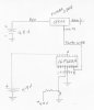
Looking for a little help. I want to control a servo moving it 180 degrees clockwise and back 180 degrees counterclockwise using a 16F628A Pic. At present when I power the pic the servo only rotates clockwise to the end. My knowledge of pics is very limited so I can use all the help I can get. I have attached a hand drawn schematic of the circuit that I am having a problem with, and the .asm code that I am using. Thanks for any help that I may receive.
Code:
 

Attachments

  • Servo circuit.jpg
    Servo circuit.jpg
    233 KB · Views: 763
  • Servocontrol2.asm
    2.1 KB · Views: 356
.asm screw up

Sorry for the code posting screw up. I will try again.

Code:
LIST	        p=16f628A
	    include			"p16f628A.inc"
	    __CONFIG	_CP_OFF & _DATA_CP_OFF &_LVP_OFF & _BOREN_OFF &_MCLRE_ON & _WDT_OFF & _PWRTE_ON & _INTOSC_OSC_NOCLKOUT		
	    
	    
	    ERRORLEVEL -302

 
		cblock	0x20
				Count
				Count1				;variables for Delay routines
				Counta
				Countb
				
				
				endc


		ORG			0x0000
		
		movlw		0x07		    ;like 16f84
		movwf		CMCON


Initialization

		banksel		TRISB			;select bank 1
		movlw		b'00100000'		
		movwf		TRISB			;Make TRISB all outputs except RB5
		movwf		TRISA			;Make TRISA all outputs, except RA5 which is input only
		banksel		PORTB			;Select Bank 0
		movwf		PORTB			;Make PORTB all low with exception of RB5 which will be Hi
		movwf		PORTA			;Make PORTA all low with exception of RA5 which will be HI (using MCLRE for reset)
		

Turn180
		movlw		d'25'
	    	movwf		Count

Forward
		bsf		PORTB,2
		call		Delay3			;delay for 2ms "clockwise motion"
		bcf	    	PORTB,2
		;call		Delay1
		call		Delay1
		call		Delay1			;delay for 18ms
		decfsz		Count
		goto		Forward

		
Backward
	    	movlw		d'55'
		movwf		Count	
		bsf			PORTB,2		;Delay for 1ms (Counter Clockwise)		
		call		Delay2
		bcf			PORTB,2
		decfsz		Count
		goto		Backward
		nop
		
		sleep


Delay1	movlw		d'36'			;Delay 18ms(4MHz clock)
		movwf		Count1
d1		movlw	    d'100'
		movwf		Counta
		movlw		d'1'
		movwf		Countb
Delay_0
		decfsz		Counta,f
		goto		$+2
		decfsz		Countb,f
		goto		Delay_0

		decfsz		Count1,f
		goto		d1
		retlw		0x00


Delay2	movlw		d'2'		    ;delay 1ms (4MHz clock) forwards
		movwf		Count1
d2		movlw		d'100'
		movwf		Counta
		movlw		d'1';
		movwf		Countb
Delay_1	
		decfsz		Counta,f
		goto		$+2
		decfsz		Countb,f
		goto		Delay_1

		decfsz		Count1,f
		goto		d2
		retlw		0x00

Delay3	movlw		d'4'		    ;Delay 2ms (4MHz clock) backwards
		movwf		Count1
d3		movlw		d'100' 
		movwf		Counta
		movlw		d'1';
		movwf		Countb
Delay_2	
		decfsz		Counta,f
		goto		$+2
		decfsz		Countb,f
		goto		Delay_2
		retlw		0x00


    	END
 
sparky72 said:
180 degrees clockwise and back 180 degrees counterclockwise
Most servo's can rotate to that degree, standard servo signals are generally timed around 90 degrees each direction and the POT used in typical servo's can at best provide 120 degrees.
 
Your 'Backward' routine will never end because you initialise 'Count' at the beginning of every loop. Put the first 2 instructions in 'Backward' at the end of your 'Forward' routine.

Verify that you are actually getting output on your pins. Have you tried to light an LED to make sure the micro is initialising and running properly?
 
Last edited:
A couple of notes on your code -

1) Bit RA5 in both TRISA and PORTA is always ignored. When RA5 is set to external master clear mode in the config word (which it already is by default), you don't internally set bit RA5 high in the PORTA register. You have to externally drive it high with a pull up resistor (hence the name "external" master clear ;) ).

2) Config word bits are all 1's by default. You only need to deal with config bits that need to be cleared.

3) Delay routines - you only need 2. One that is a fixed delay time and one that is variable by loading a value into W prior to calling the delay routine, then dropping W into the delay counter.

4) Anytime you execute a decrement instruction (either decf or decfsz) for the sake of decrementing the value residing in a register, you MUST place the F designation after the register address (or label). Example -

Code:
         decfsz               Count,F

The "F" tells the PIC to place the decremented result back into the source file. This gets rid of the "Using default destination of 1 file" assembler warning.

Here...try this code and let us know how it works -

Code:
		list		p=16F628A, r=dec, w=-302
		include		<P16F628A.INC>
		__config	_LVP_OFF & _BOREN_OFF & _WDT_OFF & _PWRTE_ON & _INTRC_OSC_NOCLKOUT		
 
 
		cblock		0x20
				Count
				Count1				;variables for Delay routines
				Count2
				Count3
 
 
		endc
 
		cblock		0x70
				W_TEMP
				STATUS_TEMP
				PCLATH_TEMP
		endc
 
		org		0x0000
 		goto		Start

		org		0x004
		movwf		W_TEMP
		swapf		STATUS,W
		banksel		0
		movwf		STATUS_TEMP
		movfw		PCLATH
		movwf		PCLATH_TEMP

;place holder for interrupt handler (in case needed)

ISRExit		movfw		PCLATH_TEMP
		movwf		PCLATH
		swapf		STATUS_TEMP,W
		movwf		STATUS
		swapf		W_TEMP,F
		swapf		W_TEMP,W
		retfie

;place look up tables here (if applicable)

Start		
		movlw		0x07		    		;disable on chip comparator
		movwf		CMCON
 
Initial
 		clrf		PORTA			;Make PORTA all low (RA5 set high externally via pull up resistor)
		movlw		b'00100000'		
		movwf		PORTB			;Make PORTB all low with exception of RB5 which will be Hi
		banksel		TRISA			;select bank 1
		movlw		b'00100000'		
		movwf		TRISB			;Make TRISB all outputs except RB5
		clrf		TRISA			;RA0-RA7 outputs, RA5 external master clear (governed by config word setting)
		banksel		PORTA			;Select Bank 0
		
 
Turn180
		movlw		25			;initialize variable 'Count' to decimal 25
	    	movwf		Count
 
Forward
		bsf		PORTB,2			;RB2 high
		movlw		2
		call		Delay			;delay for 2ms "clockwise motion"
		bcf	    	PORTB,2
		movlw		18
		call		Delay			;delay for 18ms
		decfsz		Count,F
		goto		Forward
 
		movlw		d'55'
		movwf		Count	 
Backward
	    	
		bsf		PORTB,2			;Delay for 1ms (Counter Clockwise)
		call		Delay1mS
		bcf		PORTB,2
		decfsz		Count,F
		goto		Backward
		nop
 
		sleep

Delay1mS	movlw		167
		movwf		Count1
		movlw		2
		movwf		Count2
		decfsz		Count1,F
		goto		$-1
		decfsz		Count2,F
		goto		$-3
		return

Delay		movwf		Count3
		call		Delay1mS
		decfsz		Count3,F
		goto		$-2
		return		
 
 
 		end
 
Last edited:
Pic contolled servo

Thanks, Jon Wilder and Gobbledok for the reply to my request. Jon, I reprogrammed the pic with your .asm file and now the servo will only run counter clockwise from one end to the other when I connect power to the pic. The circuit is connected as per the circuit drawing that I attached to my first post. Does the circuit look correct. Pin # 4 has a 10K Ohm resistor to vdd and a momentary switch to ground. I am trying to get this servo to travel as close to 180 degrees clockwise as possible and then counter clockwise as close to 180 degrees as possible with a single push of the momentary switch, and then go to sleep until the momentary switch is pushed again. I really appreciate the help that you are giving me.
 
Thanks, Jon Wilder and Gobbledok for the reply to my request. Jon, I reprogrammed the pic with your .asm file and now the servo will only run counter clockwise from one end to the other when I connect power to the pic. The circuit is connected as per the circuit drawing that I attached to my first post. Does the circuit look correct. Pin # 4 has a 10K Ohm resistor to vdd and a momentary switch to ground. I am trying to get this servo to travel as close to 180 degrees clockwise as possible and then counter clockwise as close to 180 degrees as possible with a single push of the momentary switch, and then go to sleep until the momentary switch is pushed again. I really appreciate the help that you are giving me.

Aha! I know exactly what the issue is.

The "wake from sleep via external reset on MCLR" will wake the PIC from sleep, but it will also reset the PIC, which will make the code execute from the beginning rather than continue running code and toggling between the forward/backward routine.

What you're trying to do is totally doable, we just need to do it differently than how you're trying to do it. We'll need to do this on the RB0/INT pin instead to keep from resetting the PIC when it wakes from sleep. Also, in order for the sleep instruction to work, we need to enable interrupts and set up the interrupt handler, which I've already set up a place holder for.

Now...I see that you're setting up RB5 as an input, then you're trying to set RB5 high in code. Inputs are EXTERNALLY driven high/low. ONLY OUTPUTS can be driven high/low in software. Inputs are driven high/low EXTERNALLY. However, in your schematic, there is nothing connected to RB5 so we're going to set that up as an output and drive it low along with the rest of PORTB on initialization.

Give me a couple hours with the code and I'll have something for you.
 
Last edited:
OK...relocate the button switch to RB0/INT (no pull up resistor needed since I turned on the internal weak PORTB pullups) in order for this to work. But here is the new code -

Code:
;*****************************************************************************************
;*****************************************************************************************
;**											**
;**			Header Information						**
;**											**
;*****************************************************************************************
;***************************************************************************************** 
 		
		list		p=16F628A, r=dec, w=-302
		include		<P16F628A.INC>
		__config	_LVP_OFF & _BOREN_OFF & _WDT_OFF & _PWRTE_ON & _INTRC_OSC_NOCLKOUT		
 
;*****************************************************************************************
;*****************************************************************************************
;**											**
;**			Variable Declarations						**
;**											**
;*****************************************************************************************
;***************************************************************************************** 

		cblock		0x20
				Count
				Count1			;variables for Delay routines
				Count2
				Count3
		endc
 
		cblock		0x70			;interrupt handler software stack
				W_TEMP
				STATUS_TEMP
				PCLATH_TEMP
		endc

;*****************************************************************************************
;*****************************************************************************************
;**											**
;**				I/O Pin Declarations					**
;**											**
;*****************************************************************************************
;*****************************************************************************************

#define		BUTTON		PORTB,0
#define		SERVO		PORTB,2 
 
;*****************************************************************************************
;*****************************************************************************************
;**											**
;**			Reset Vector							**
;**											**
;*****************************************************************************************
;***************************************************************************************** 
 
		org		0x000			
 		goto		Start

;*****************************************************************************************
;*****************************************************************************************
;**											**
;**			Interrupt Handler						**
;**											**
;*****************************************************************************************
;***************************************************************************************** 
  
		org		0x004			
		movwf		W_TEMP			;push W
		swapf		STATUS,W		;push STATUS
		banksel		0			;bank 0
		movwf		STATUS_TEMP
		movfw		PCLATH			;push PCLATH
		movwf		PCLATH_TEMP
 
		btfsc		0x30,0			;is backward flag set?
		goto		Backward		;yes, run servo backward
 
Forward
		movlw		25			;no, initialize variable 'Count' to decimal 25
	    	movwf		Count
 		
		bsf		SERVO			;RB2 high
		movlw		2			;delay 2mS
		call		Delay
		bcf	    	SERVO
		movlw		18
		call		Delay			;delay for 18ms
		decfsz		Count,F
		goto		$-7
		bsf		0x30,0			;set backward flag
		goto		Release
 
Backward 
		movlw		d'55'
		movwf		Count	 
 
		bsf		SERVO			;Delay for 1ms (Counter Clockwise)
		call		Delay1mS
		bcf		SERVO
		decfsz		Count,F
		goto		$-4
		bcf		0x30,0			;clear backward flag 
 
Release		movlw		50		
		btfss		BUTTON			;has button been released?
		goto		$-1			;no, check again
		call		Delay			;yes, debounce
		btfss		BUTTON			;is button still released?
		goto		$-5			;no, loop back and wait again
		bcf		INTCON,INTF		;clear RB0 interrupt flag
 
ISRExit		movfw		PCLATH_TEMP		;pop PCLATH
		movwf		PCLATH
		swapf		STATUS_TEMP,W		;pop STATUS
		movwf		STATUS
		swapf		W_TEMP,F		;pop W
		swapf		W_TEMP,W
		retfie					;return
 
;*****************************************************************************************
;*****************************************************************************************
;**											**
;**			Initialization Routine						**
;**											**
;*****************************************************************************************
;***************************************************************************************** 
 
Start		
		movlw		0x07		    	;disable on chip comparator
		movwf		CMCON
 		clrf		PORTA			;PORTA default low (RA5 set high externally via pull up resistor)
		clrf		PORTB			;PORTB default low
		banksel		TRISA			;select bank 1
		clrf		TRISA			;RA0-RA7 outputs, RA5 external master clear (governed by config word setting)		
		movlw		b'00000001'		
		movwf		TRISB			;Make TRISB all outputs except RB0
		movlw		b'00010001'		;RB weak internal pull ups on, interrupt on falling edge of RB0/INT
		movwf		OPTION_REG		;Timer 0 Clock source = Tcy, 1:4 prescale
		banksel		PORTA			;Select Bank 0
 
		bcf		INTCON,INTF		;clear RB0 external interrupt flag		
		bsf		INTCON,INTE		;enable RB0 interrupt
		bsf		INTCON,GIE		;enable unmasked interrupts

;*****************************************************************************************
;*****************************************************************************************
;**											**
;**				Main Program						**
;**											**
;*****************************************************************************************
;***************************************************************************************** 
 
		sleep					;sleep while INT0 = 1
		nop
		goto		$-2			;place PIC in sleep mode upon return from interrupt

;*****************************************************************************************
;*****************************************************************************************
;**											**
;**				Delay Routines						**
;**											**
;*****************************************************************************************
;***************************************************************************************** 

Delay1mS	clrf		TMR0
		bcf		INTCON,T0IF
		btfss		INTCON,T0IF
		goto		$-1
		return

Delay		movwf		Count1
		call		Delay1mS
		decfsz		Count1,F
		goto		$-2
		return

 		end

Also, take note on how I organized the code so that it's easy to find each section of the code. This is a very good coding habit to get into. IMHO you can NEVER overcomment code. Also take note of the code structure as well. Notice I do not enable interrupts until the init code has been completed.

If you have any asm coding questions feel free to ask them and I am more than willing to help.
 
Last edited:
pic to servo

Hi Jon. Still no go. I checked the voltage at RB2 and it only reads 10 mv. Should this voltage not be around 5v? Both battery voltages are 5.2 V. I have placed the momentary switch between RB0/INT and vss with no resistor and it also has no effect when I activate it. Sometimes when I make the battery connection to the pic the servo will move slightly clockwise and then other times it does not move at all. Thanks again for all the work that you have gone through to help me get this thing going.
 
OK I just made some more corrections to the above code. Re-copy and paste it, then assemble and try it again.
 
pic to servo

Still a no go Jon. I am getting 10mv at the output pin RB2. Not enough to even light a LED which I tried.
 
Last edited:
OK...before I look at the code, can you measure the voltage on RB0 and tell me what it is?

Also, do you have a pull up resistor on RA5?
 
Last edited:
pic to servo

No, I did not have a resistor connected to RA5. The voltage at RB0 is minimal, around 5mv. However I did connect a 10k ohm resistor to RA5 and now when I push the reset button the servo will move a very short distance clockwise and stop, then when I push the reset button again the servo moves a very short distance counter clockwise and stops.
 
Last edited:
No, I did not have a resistor connected to RA5. The voltage at RB0 is minimal, around 5mv. However I did connect a 10k ohm resistor to RA5 and now when I push the reset button the servo will move a very short distance clockwise and stop, then when I push the reset button again the servo moves a very short distance counter clockwise and stops.

That would be your issue right there. RA5/MCLR is currently functioning as MCLR. Without referencing RA5 to Vdd either via a pull up resistor or a direct connection to Vdd, this leaves MCLR undefined, so the PIC doesn't know whether to run or reset itself. It's probably stuck in reset.

RA5/MCLR is input only. It CANNOT be set high in code. It MUST be driven high externally via hardware.

Do either one of these 3 things -

1) Place a pull up resistor between RA5/MCLR and Vdd
2) Connect it to Vdd directly or
3) Add _MCLRE_OFF to the configuration word

Retest and see what she does.
 
Last edited:
OK Jon, I connected a 10K ohm resistor to RA5 to vdd. The servo now moves a very few degrees clockwise when I push the reset button and then stops. When I push the button again the servo moves counter clockwise and stops. It just keeps moving back and forth a few degrees with each push of the button. The way I would like the servo to work is to have it move in both directions with just one push of the button.
 
Last edited:
OK...before we go any further, we can simplify this by using the PWM module on pin RB3. But first, I need to know -

When you say you want the motor to move in both directions, do you mean you want it to run in one direction on a button press, then run in the opposite direction on a button release?
 
Last edited:
I would like to again state, one more time; 'standard servo throws' are 90 degrees from center. No matter what code your write this servo will never be able to rotate both +180 and -180 degrees from center.

**broken link removed**

I don't care what's wrong with the code, you can't fix a physical limitation.
 
Last edited:
Pic to servo

Jon, with one push of the momentary switch I want the servo to move one direction as far as possible and return to the starting point, then go to sleep, . I would be happy if I could get 130 or 140 degrees of travel in each direction. Thanks for hanging in there with me.
 
pic to servo

This is in response to Sceadwian's post. Sorry for the misunderstanding. I do not want the servo to travel from centre 180 degrees but rather start from one extreme end of the servo travel to the other end of the servo travel and back to the starting point, with one push of the momentary switch.
 
Last edited:
Status
Not open for further replies.

Latest threads

Back
Top