Continue to Site

Welcome to our site!

Electro Tech is an online community (with over 170,000 members) who enjoy talking about and building electronic circuits, projects and gadgets. To participate you need to register. Registration is free. Click here to register now.

  • Welcome to our site! Electro Tech is an online community (with over 170,000 members) who enjoy talking about and building electronic circuits, projects and gadgets. To participate you need to register. Registration is free. Click here to register now.

Series Time Delay circuit question

Status
Not open for further replies.

zcream

New Member
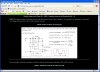
Hi! I am connecting 30 devices in series. I am trying to delay the input pulse 4-10ms for each device. Thus Device 1 is 4ms delayed from Device 0, Device 2 is 8ms delayed from Device 0 etc.

Since the delay is small enough and does not have to be precise I am thinking of using a simple RC delay.
However, I am unsure what happens when you connect 30 RC delay circuits in series.
There is probably feedback, and due to capacitances in parallel the net capacitance will reduce..
How can I add a "buffer" so that once a signal progresses from Device 0 to 1 to 2, it is unaffected by the R and C values "behind" it ??
I hope its clear - I can add more details if its not..

In summary, a circuit where various points in series need an increasing time delay from the origin..
 
You need to tell us about the output of the first device and the input of the second device.
We need to know the impedance of the input of the second device.
 
The circuit is a 3.6V Lithium battery in series with a switch. This output is connected to 30 cameras in series..
The camera firmware recognizes a signal of 3V as a shutter release. Thus, when the switch is pressed, the circuit completes and a shutter release signal is registered..

I want the cameras to release shutter at a time delay from each other - say 4-10ms. It does not have to be very precise. Thus I was thinking of a RC circuit before each camera to delay the signal..

So I guess the load is essentially the resistance of the camera..Not sure what that is - if its important I can take a reading on a multimeter..
 
This is really an application for a microcontroller as you may want the signal to be present for a short period of time for each camera.
 
You would need a microcontroller with 15 outputs. Each output would have an R-C delay of 4mS for a second output. This way you would get 30 outputs, each delayed by 4mS.
We just need to know how much current is required to trigger each camera.
 
If you don't want to go pic

you could go with 3-cd4017's
then you don't have to do any fancy micro-controllers.
just depends on output requirements for the shutter release.
Just my first thoughts.
an astable 555 might work.
R1 = 100K, R2 = 600K, cap1 = .01uf = .000004 seconds high and .000004 seconds low.
a 53% duty cycle
 

Attachments

  • Capture2-22-2009-11.58.18 AM.jpg
    Capture2-22-2009-11.58.18 AM.jpg
    191.8 KB · Views: 164
I gots to many 0's?

I wasn't sure so I did a web search and thats what it came up with = 5 0's
how many is it supposed to be??
 
Restarting thread

Hopefully some of the posters are still interested in this.
I put the project at the backend, then started it again recently.
Here is the description.
>>
So, if C1, C2 ... Cn are cameras
and D1, D2, ... Dn are delay circuits
and Pulse denotes the ON trigger pulse (just a simple switch I will turn on and off)

The circuit is
Pulse --- D1-C1---D2-C2--...--Dn-Cn

How precise does your delay have to be?
10ms precision

How wide is the pulse?
100ms per camera. Input Pulse can be held high as needed.

Does the pulse repeat?
Nope. 1 pulse activates C1, which propagates to C2 then to C3. The delay circuits D1..Dn are initially open and then stay closed to allow the voltage to trigger to the next one.
>>

Is there really a PIC with say 60 outputs that could drive all these ?
 
One pulse triggers the 60 outputs if I am reading this right?
If so then yes a simple 4017 chain would work IMO but a pic would be ideal.
As for 60 outputs a 74hc595 comes to mind.
 
Back towards the beginning:

The circuit is a 3.6V Lithium battery in series with a switch. This output is connected to 30 cameras in series..
The camera firmware recognizes a signal of 3V as a shutter release. Thus, when the switch is pressed, the circuit completes and a shutter release signal is registered..

Now I don't know if this is true of most cameras, all cameras or a case by case camera basis but I can speak for a few. I have both a Canon EOS 10D and a Canon EOS 7D. They each use the same configuration for remote focus (in the auto focus mode) and remote shutter release. Their configuration can be found here. If I read from either the auto focus pin or the shutter release pin to ground I see about 3.3 volts present. Placing either of those two pins to ground performs their assigned action. Essentially placing either pin to a logic low triggers it. There is no need for an external voltage. The camera provides everything.

Based on my own cameras to remote trigger the shutters it would be a matter of using a switch type device to place the designated pin to a logic low (ground). I would think an NPN type transistor could do this, along the lines of a 2N3904 or 2N2222. That is a guess but I doubt any current to speak of is involved in this. The 3.3 volts provided by the camera is likely through a pull up resistor since it gets placed at ground.

I also do not know as I have not experimented with it how long the designated pin must be held at logic low for it to work. That would be another consideration.

As to the use of the good old 4017 Decade Counter / Divider. The 4017 will sequentially make 1 of 10 outputs go high for each incoming clock pulse. Those outputs could in turn likely drive transistors as I mentioned earlier. The 4017 can be setup to count to N and halt or count to N and recycle. The chip does offer a CO (Carry Out) pin to allow cascading.

If I wanted to sequentially fire the shutter release of ten cameras configured as in my link, this would be easy to do. Cascading two 4017s would seem a good way to increase the outputs from 0 to 9 to 0 to 99 but there is a problem I think. The first chip would count 0 to 9 and the CO would increment the second chip up one count. Then the first chip would repeat the count and increment the second chip up another count. At that point the first 10 cameras would want to or be triggered to shutter release again.

I am sure this could be done using a PIC but will leave that for those like BlueRoom who live and breath PIC chips. :) I would likely create a disaster using them for this application.

Ron
 
zcream,

Do you have a Multimeter? If so, do the following two tests and report back: If not, borrow/buy one.

1. Put the meter in DC volts mode, turn on the camera, and measure the voltage between the shutter release pin and the camera's ground .

2. Put the meter in the DC mA mode, and measure the current that flows out of the release pin to the camera's ground. This should take a picture as you connect the meter probes.
 
Last edited:
Status
Not open for further replies.

Latest threads

Back
Top