Continue to Site

Welcome to our site!

Electro Tech is an online community (with over 170,000 members) who enjoy talking about and building electronic circuits, projects and gadgets. To participate you need to register. Registration is free. Click here to register now.

  • Welcome to our site! Electro Tech is an online community (with over 170,000 members) who enjoy talking about and building electronic circuits, projects and gadgets. To participate you need to register. Registration is free. Click here to register now.

series and parallel circuits

Status
Not open for further replies.
Your circuit diagram link

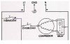
I checked out your link to your diagram, I don't understand any of it. I have forgotten a lot of what I learned in the past. I guess I need to start over again and relearn some of it. I do have a question about the circuit I provided, is the motor windings considered a parallel bank. I notice there are what is called Branches and Banks. I have an idea, but a true expert might explain it better. Thanks! My mind will fry a crispy afterthought!
 
Hi,

Well, you had a look anyway.
Doesnt matter if you followed it or not,
but just looking through it would have shown you
that different 'loops' can have shared parts that interact
sometimes in curious ways.

Understanding electronic schematic diagrams can be quite involved,
which is why i suggest starting with simple stuff, until you get
used to working with it.

**************

As to your motor windings, I don't think those motor windings would
be referred to as a 'Parallel bank' ... but its not a term i've heard.

Branches and banks ? ... sorry, i haven't heard this term before either.

Maybe someone else here is familiar with the terms, and can let us
know what it means.

**************

The windings on your motor are not the same, only the run winding is
for continual use, the start winding is only for starting, and its
(normally) a heavier winding.

Best of luck with it, John :)
 
Diagram

I am not done with your diagram yet. I need to look at it, analyze it and that is the way I do things. If at first I can't understand something, I'll try to find a way to figure it out, and I usually do, without anyone helping me. But I do appreciate it, actually I can figure it out, but I use different methods. Anyhow, there are branches in parallel and then there are banks in parallel. A branch is actually a voltage divider, and a bank is basically a divider, but looks more like a series circuit with two resistors side by side. No, I am no expert, but the motor windings look a lot like a branch. That is kind of why I was confused, the motor windings look like they are in the path of a series circuit yet they are parallel, being side by side. Well, like I said I am no expert, but that is the way I see it, but your explanations on the motor and relay circuit have helped me a lot, and saved me a lot of time. Actually, I was checking out some software that has an electronic lab with it, you know kind of like a virtual lab where you can manipulate the components to test your circuit analysis. Do you know of any good software programs like this, I have seen some, but there kind of expensive. I thought a real type of lab might help me to understand the series parallel thing a bit better. Well, Thanks, and I'll keep checking back to see whats new. A question on the circuit I provided? To me it looks like the fuse or overload protector is in parallel with the run winding, but other sources tell me it is in series with both windings. I can understand, that if the motor windings aren't kicking in properly, both, it would trip the overload. But since the current has to go through the run winding first then the relay to the start winding, without a breaking point, and there was a hangup, there would also be a trip of the overload. On the other hand if the current were to only go through the run winding and since current is flowing through the run winding without the aid of the start winding, wouldn't this also cause the overload to trip. Just some guesses, what do you think!
 
Hi,

A question on the circuit I provided? To me it looks like the fuse or overload protector is in
parallel with the run winding, but other sources tell me it is in series with both windings.


There are three states or conditions that this motor circuit can be in.


AT REST.
--------
At rest there would be continuity through the overload device, the run winding and the coil of
the special purpose relay.
At rest there would be no continuity through the relay contacts, which would be open, so there
would be no current path for any current to go through the start winding, which would not be
'in circuit' in the at-rest state.

The feed to the motor and overload device may or may not come via the thermostat,
which is shown as 'normally open' so its reasonable to assume the feed to the motor assembly
comes from elsewhere.


STARTING.
---------

When starting, the special purpose relay would operate from the current going through the run
winding, and its contacts would close.
With the contacts closed, the start winding is effectively in parallel with the run winding.

The coil of the special purpose relay is not normally very many turns of wire and has almost
no effect on the run winding, and remains in circuit throughout.
The starting current is higher, and the special purpose relay responds to the higher current.

During this starting period, the start and the run windings are effectively in parallel,
and as a pair would be considered in series with the overload device.

The overload device and the motor windings would make a series-parallel arangement during
the starting period.


RUNNING.
--------

Once the motor has run up to its operating speed, the current drawn by the motor reduces and
the special purpose relay drops out, and it's contacts open.
Then the start winding is no longer 'in circuit' and we are left with three items in series,
the overload device, the run winding, and the coil of the special purpose relay.

So the state of the circuit changes from series to series-parallel, and back to series by
the action of the special purpose relay.

*********************

On the other hand if the current were to only go through the run winding and
since current is flowing through the run winding without the aid of the start winding,
wouldn't this also cause the overload to trip


Sometimes yes. These overload devices usually have an interval before they operate, so that
higher initial loads dont necessarily cause them to trip.
If the start relay or the start winding were to fail, then yes that would mean that the current
through the run winding would not reduce, because the motor would not spin up to speed.
This would cause the run winding to get warm, maybe even hot.
If the run winding got too hot, it may short and cause the overload device to trip.
Or maybe the overload device has been chosen to respond if the motor doesn't start within a
given time.
The interval on these devices is usually some hot element made to cause a trip.
They may or may not be re-settable.
There are many types.

Cheers, John :)
 

Attachments

  • Motorwhite .JPG
    Motorwhite .JPG
    19.1 KB · Views: 792
Last edited:
Motor and circuits

Wow! You know your stuff! Actually much of what you have explained in this reply, I kind of was on the right track. And you have verified much of what I was thinking, and I really don't know what to ad to it, except it sounds like you have explained it well, and it is a great help, Thanks very much. I am still looking over your material and the others who have replied, I guess Ol Tesla, I think that's how you spell his name, had a lot on his mind when he built his first motor. Cause I can see, though a simple design today, must have been very confusing in the early days.
 
Thank you Electromagnaman,

I'm glad to have been some help.

Cheers, John :)
 
Status
Not open for further replies.

Latest threads

New Articles From Microcontroller Tips

Back
Top