Continue to Site

Welcome to our site!

Electro Tech is an online community (with over 170,000 members) who enjoy talking about and building electronic circuits, projects and gadgets. To participate you need to register. Registration is free. Click here to register now.

  • Welcome to our site! Electro Tech is an online community (with over 170,000 members) who enjoy talking about and building electronic circuits, projects and gadgets. To participate you need to register. Registration is free. Click here to register now.

series and parallel circuits

Status
Not open for further replies.

electromagnaman

New Member
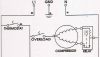
I have the hardest time distinguishing a series circuit from a parellel circuit. I know what a series circuit looks like and a parallel circuit, and both, but when i try to interpret them in a schematic or diagram I have trouble. Like one I am now trying to read, which has a two winding motor with a relay switch. It is in fact, a refrigerator motor, or compressor. But I can't tell if both the start and run windings are either in series or parallel. I think the motor windings are in parallel, and I believe the coil of the relay is in series with the run winding, but is it in series with the start winding or are both the contacts of the start and run windings in parellel with the coil and switch of the relay. It seems a bit confusing. And if the compressor motor windings are in series inside the motor, wouldn't the windings then be in series in the circuit diagram. Anyone know of any answers or any information to read up on for this type of configuration. Thanks!:confused:
 
Hi,

Yes, some of these configurations can be confusing.
Please describe the relay associated with the motor some more.

A lot more actually.

John :)
 
series parallel motor winding, relay

My printer is down right now, I'll try and upload a picture, I'll draw myself, it isn't a complicated symbol. Give me a little bit of time, I'll load it soon. I am not sure about uploading pics here. Any info on that would be appreciated, I will check the forum out. Man I am glad this forum is here, I can really learn a lot . I have been wanting to figure these diagrams out for a long time, electronics is kind of a hobby of mine, actually both Ac and DC circuits. Actually I think I may have it figured out, but some help from some experts would be a big plus. Thanks!
 
Hi electromagnaman,

differentiating between parallel and serial connected electronic components just image they were water hoses.

To increase the total diameter of a water hose you use two of them parallel (assuming that there is no bigger diameter hose available). Looking at them there is one important thing to note: both hoses have the same common connection at their inputs and also on their outputs.

A series connection can be understood as just to extend the pipe to a certain length. One output is connected to the following input.

Comparing the water hoses there is just the same effect as with electric power. Paralleling two hoses they will share the total pressure, likewise two paralleled resistors divide the total current into two separate currents. With two resistors of equal values the total current flow is divided by two, one half for each resistor.

Two resistors in series will increase the total resistance, hence decrease the current (as water hoses decrease the water flow due to resistance, one of the reasons why pumps are used in pipelines at every few km distance.) and also work as a voltage divider. Again using two equal resistors the voltage drop across both resistors equals the supply voltage and at the junction of these two resistors you will have half the supply voltage.

Regards

Boncuk
 
I keep saying it a openminded electronic electrician will be a good plumber also and visa versa ;)

Robert-Jan
 
simple problem

I am gona give this a try. Actually I was going to redraw this, to see if my assumption was correct, but I will post this diagram to kind of give an idea. I can see that the thermostat and overload are in series, and I know the windings of the motor are in series inside the motor, and that they are in parellel on the diagram, but how is the relay wired, I see it is across the run and start windings and is suppose to be in series with the run winding, but when the switch is engaged to the start winding would it be series or parellel on the relay to both motor windings, and I know that the relay switch is only momentarily engaged to energize the start winding that in turn starts the run winding.. I hope the pic is big enough to view. Thanks again, for any ideas.
 

Attachments

  • lastscan.png
    lastscan.png
    323.6 KB · Views: 288
Last edited:
electromagnaman said:
I can see that the thermostat and overload are in series,
That's OK, they are both in series with the motor.

electromagnaman said:
and I know the windings of the motor are in series inside the motor, that they are in parellel on the diagram
They are not in series, and they are not in parallel :confused:

(To be in series or parallel the two [windings, resistors, or whatever] should have only two external terminals)

electromagnaman said:
and , but how is the relay wired, I see it is across the run and start windings and is suppose to be in series with the run winding, but when the switch is engaged to the start winding would it be series or parellel on the relay to both motor windings, and I know that the relay switch is only momentarily engaged to energize the start winding that in turn starts the run winding..

The relay's coil is in series with the run winding (actualy, it is only a few turns of heavy gauge wire)

The relay's contacts are in series with the start winding.

The run winding + coil series is in parallel with the start winding + contacts series.

When the thermostat closes the relay's contacts are open, and only the run winding is connected. As the motor is stopped, the current is very high (5 to 6 times the normal run current) and this current in the coil closes the relay's contacts.

When the relay's contacts close there is current in the start winding and the motoir starts.

When the motor starts the run winding current drops to the normal run current, and the relay opens.
 
Amazing

Well I see some of what your saying, I still don't get some of it. Like the run and coil relay circuit being in parellel with the start and switch contact circuit. The reason I mentioned that the run and start windings were in series inside the motor, is because I thought from much of what I read that most motor windings are connected in series, a continious run of wire with North and South reversed with each winding. Is there another way to redraw the circuit to understand what your saying about the run and coil winding being in parellel with the relay switch contact and start winding circuit. Yea I'm learning, but when I finally understand it, I'm a gona celebrate. With a cold beer and some hot solder.
 
electromagnaman said:
Well I see some of what your saying, I still don't get some of it. Like the run and coil relay circuit being in parellel with the start and switch contact circuit.

Two (or more) parts of a circuit are in parallel if they are connected to the same pair of "nodes" (the little dots in the schematic). They will have allways the same voltage across them.

In this case, both are connected between the right side of the overload and the neutral.

electromagnaman said:
The reason I mentioned that the run and start windings were in series inside the motor, is because I thought from much of what I read that most motor windings are connected in series, a continious run of wire with North and South reversed with each winding.

That's not allways the case. It depends on the type of motor.

This type of motors (1 phase split phase induction motors) have allways two windings (set at 90º), and they are wired in parallel (sometimes with a capacitor in series with one of the windings).

Each of the windings is "a continious run of wire with North and South reversed with each winding."
 
please describe the relay a little better.

John :)
 
relay

Not sure, it is a regular coil type, I think it is called an open face relay, while there is another one called a closed relay that is referred to as a PTC relay, this one is a simple relay with one coil and a plunger type mechanical device in it, for a refrigerator or a wine cooler type of appliance. I'll check to find out for sure, but I thought I might mention that with the two windings in series with the relay coil and the relay switch contacts, I was thinking that if you have two series resistors side by side, wouldn't that be a parallel combination, as most series resistors are in line with each other, I hadn't thought of looking at the two motor windings like that before. Oh well, it's a getting a little clearer. I'll Keep Hammering away! I have done some plumbing, a little messier but not quite as mind boggling. Thanks! Some real experts out there!
 
Last edited:
Hi Electromagnaman,

I will try to explain how this type of motor and relay work, assuming
that the relay is the type that i think it is.
Having looked carefully at the diagram you posted, i am going to guess
that the relay has a weighted slug which slides upwards when the relay
coil is operated.

I think black for live and white for neutral was an old German wiring
colouring, but of course that could just be coincidence.

It looks to me that with the relay at rest, the weight of the slug is
keeping the contacts open, and the weighted slug is lifted vertically
when enough current goes through the relay coil to close the contacts.

If this is the arrangement, and i think that it is, then this relay is
a type that is only made for this sort of job, and is not an ordinary
type of relay at all.

When the motor starts to spin, and its impedance increases, the current
drawn by the 'Run' winding decreases and the relay can no longer carry
the weighted slug and the contacts on the 'Start' winding open.

This type of relay normally has only enough turns to do its job.

Since for some reason i think you would like to know how the motor
actually works, i will go into that next.

John :)
 
Hi Electromagnaman,

THE MOTOR.
This type of motor will run equally well in either direction, when its
running only the 'Run' winding is driving it.

*****************

If the 'Start' winding does not engage when the motor is switched on,
so that only the 'Run' winding is supplied with electricity,
then the motor will 'HUM' and will not start to turn.

This is because the 'Run' winding is pushing and pulling at the rotor,
but it is not imparting any rotational effect, just pulling and
pushing at the supply frequency.

If the rotor is then given a little spin in either direction, the motor
would then run up to running speed (assuming it is free to do so) in
the direction of the initial spin.

******************

This is where the 'Start' winding comes into play.
It can be wired in either direction to make the motor run either way.
It only has to be supplied for starting, but it has to be a distinctly
different inductance to the run winding to have the best effect.
And of course its usually mounted at right-angles to the 'Run' winding.

To Be Continued ...
John :)
 
Hi Electromagnaman,

THE ROTATIONAL EFFECT.
This is probably one of the more difficult aspects to grasp.
So i will try to explain it clearly.
(i have already re-written this quite a few times)

*****************

In the picture you posted, the windings are shown at an angle, I would
expect them to be at 90 deg, although they needn't be, but 90 degrees
should give the best results.

*****************

I am going to assume you have a working knowledge of magnets, and coils
and some understanding of how a winding behaves like a magnet, and that
reversing the current in a winding also reverses it's magnetic field.

*****************

Allow me first to mention the type of motor that has two very similar
windings, one usually fed via a capacitor.

If the two windings were simply fed from the same source,
then they would both act in unison pulling and pushing together on the
rotor, but without any rotational effect, as from the same source the
rise and fall of the magnetism would be synchronised.

If they were both fed from the same source, the rise and fall of the
magnetism would be somewhere between the two windings, but it would
have no rotational effect.

This is why one of the windings is fed via a capacitor, as this will
introduce a change in the timing of the magnetism's 'rise and fall'.
This puts it 'out of step' with the magnetism in the other winding.

This gives a 'Rotational effect' to the magnetic fields around the
rotor, and sets it running up to the motor speed.

****************

Now the motor you have there has no capacitor, but it has a 'Start'
winding which again, has to be 'out of step' with the 'Run' winding.

With this type of motor that is done by having a distincly different
inductance, the start winding is typically a heavier winding taking a
little more current than the 'Run' winding.

The different inductance causes the current in that winding to rise
and fall at a slightly different time to the current in the 'Run'
winding.
Even though they are connected in parallel to the same source, the
currents inside the two windings are not 'in step' because they are
different inductances.

Once the rotor starts to spin up, the start winding drops out, and the
motor runs up to its running speed.

****************

I have tried to cover the how and why, if my explanation is incorrect
i feel sure someone will set it straight, i hope i have described it
well enough for you to grasp the principles.

If something wasn't clear just say so and myself or someone else will
try to clear it up.

****************

Regards, John :)
 
electromagnaman said:
I know this is mainly for experienced techs, or middle of the road at least.
:

i do disagree with this one
everybody is welcome to ask if he has a serious technical problem no matter wat the level is
It's only that the people here are not doing sombody's home work from school

an other thing is if you want to learn something you need sombody who knows more than you ;)

Robert-Jan
 
Motors and relays

John1 and the rest who have given there expert opinions, You have explained it well, actually I know most of what your saying. And I deleted a few of my other messages to avoid any confusion on my part. But, no I am not going to school, I just like Electricity and Electronics. I do fix things, from time to time for friends and acquaintences, and I fix things at work, and also I work on electronic things I own. So, it is more of a hobby, and I like to learn, we all are always learning, there is always something new to learn for anyone, schooled or not. I think it may be a good idea to include a section on reading schematics, because I believe a lot of people would benefit from it, newbies as well as pros. Oh well, I do appreciate the help, you have explained it well. Thanks again!
 
Last edited:
Hi Electromagnaman,

Thank you for saying i have explained it well.
It was re-written several times.

Interpreting schematics will come with practice,
but understanding how the parts of circuits interact with each other
is not so easy.

Have a read through this page a few times,
https://www.romanblack.com/smps/smps.htm
to get an idea of how a circuit can have a few different operations
happening, to produce the desired result.

The sequence of events in this circuit are shown,
and the way different "loops" are shared is illustrated.

Many circuits have curious interacting paths like this.
Some circuits can take a bit of effort to get an idea of whats going on.

***********

Start with simple stuff, and get used to working with it,
Electronics can be a very absorbing hobby.

Best of luck with it, John :)
 
Status
Not open for further replies.

Latest threads

Back
Top