Continue to Site

Welcome to our site!

Electro Tech is an online community (with over 170,000 members) who enjoy talking about and building electronic circuits, projects and gadgets. To participate you need to register. Registration is free. Click here to register now.

  • Welcome to our site! Electro Tech is an online community (with over 170,000 members) who enjoy talking about and building electronic circuits, projects and gadgets. To participate you need to register. Registration is free. Click here to register now.

serial rs232 cable help?

Status
Not open for further replies.

BryWY

Member
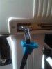
I am wondering if you could take a few minutes to assist me as I am in a bit of a bind ...I live in a remote area where I do not have access to a computer outlet where I can go out an buy a replacment cable for my Desay master vinyl plotter which I have pending jobs get done asap.

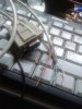
I accidently broke the male end going to my plotter off my cable. I found a generic male end all wires one color I would like to use. So I spliced the cable and found there are 7 wires in the cable red white brown green blue yellow and copper on outside.

I am wondering where I can g to find the correct wiring configuration ...any assistance you could provide would be much appreciated.

Thanks
 
Search the internet for "serial cable pin out"
There are two options. In this picture 2-3 and 3-2. But some are 2-2 and 3-3.
1_serial_cable_pinout_g_resized_1286276573311.GIF
 
A few things would help:
Assume serial
Assume D style connectors
In this case, pins or sockets determine male or female

Post a pic of the plotter connector

You can't screw up RS232 in terms of connections. You won't hurt anything if they are connected wrong. Manufactures have made lots of mistakes over the years.

1. Pins or sockets in the connector on the plotter
2. # of pins (could be 9 or 25)

1. Assume 9 pin on the PC, possibly through a USB to serial converter?
2. Probably few things woul a 9 pin male
3. They are eroneously called a DB-9, but they are really DE-9 connectors.

If you know if the plotter is a DTE or DCE device that would be cool.

So, you likely need
DTR
DSR

TXD
RXD
SG

DSR
DTR

PG (protective ground or the shield) - One side only is good

If you can measure the voltage from SG to DSR nd SG to DTR with the plotter on, that should tell us if it's a DTE or DCE.

You likely need a standard serial printer cable to either a 9 pin or 25 pin connector.

The gender used to work

Believe it or not, the wires may actually have numbers written on them. Look carefullly.
 
It is 9 pin ...male from plotter to pc 9 pin female (I would like to convert it to usb eventually) to use it on my laptop.
Tried standard universal did not work says on plotter must be sr 232...will double check

will post pic in a few minutes....
 
Rs232 is the most abused non-standard "standard that ever was.

I am not quite sure what you are saying here, are you describing the cable?
It is 9 pin ...male from plotter to pc 9 pin female

However, I guess that on the computer is a 9 pin male connector, if the connector on the plotter is a 9 pin female, try a straight through connection.

ie.

Pin 1 to pin 1
Pin 2 to pin 2
etc, all the way to
.
.
.
Pin 9 to pin 9

JimB
 
**broken link removed**

You don't need pin #1 or Pin #9. That will give you 7.
Ideally, the shield can go to one of the chassis at ONE end only.

Straight thru makes the most sense. 2-2 ; 3-3...8-8
 
just tested the regular generic serial cable that doesn't work with and it is pin for pin straight through so must be a null modem cable
cleardot.gif
 
Null modem is not straight through, the connections are crossed for handshake etc. As in post #2.
Max.
 
just checked pin 5 and 7 with volt setting on 10 dc made needle redline....not exactly sure how to use vom
 
Be careful: The Pin numbering is weird and not expected.

Your empty pins should be one on one row and one on the other at opposite ends. (diagonal).
 
my little ribbon cable that i plug in plotter male has number one pin with white stripe...now what configuration would you suggest i try?
 
just checked pin 5 and 7 with volt setting on 10 dc made needle redline....not exactly sure how to use vom

The REAL Rs232 had voltages of -25 and +25; Typically you see +12 and -12. Between +3 and -3 is the dead zone. Things get weird when the levels are +-5V and thing get weirder yet when you have inverted TTL 3.3 and 5V. You should never see that.

I'm initially interested in pin 5 to 4 and pin 5 to 6 on the plotter. Pin 5 is likely connected to chassis. No cable attached, but plotter on.
 
We definitely need a couple of pictures. There is an Upload a File.

So, your plugging in a 9 pin ribbon to a 9 pin ribbon with D connectors on them?

Basically, they are meant to be squished together because they are IDC or Interdigitated contacts. They don't make very good null modem cables.
 
the cable that worked and the ribbon cable temporary fix
 

Attachments

  • 20160407_002709.jpg
    20160407_002709.jpg
    440.1 KB · Views: 422
  • 20160407_002821.jpg
    20160407_002821.jpg
    449.5 KB · Views: 313
  • 20160407_002926.jpg
    20160407_002926.jpg
    475.7 KB · Views: 309
Status
Not open for further replies.

New Articles From Microcontroller Tips

Back
Top