Continue to Site

Welcome to our site!

Electro Tech is an online community (with over 170,000 members) who enjoy talking about and building electronic circuits, projects and gadgets. To participate you need to register. Registration is free. Click here to register now.

  • Welcome to our site! Electro Tech is an online community (with over 170,000 members) who enjoy talking about and building electronic circuits, projects and gadgets. To participate you need to register. Registration is free. Click here to register now.

Serial ICD2 Clone PCB available...

Status
Not open for further replies.

Mike - K8LH

Well-Known Member
Just exchanged emails with that eBay seller in Thailand and he said he'd sell his blank Serial ICD2 Clone printed circuit boards for $12 (USD) plus $5 (USD) shipping...

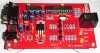
It's a decent looking board (picture below) and it sure would be a lot easier and more fun than prototyping one from scratch...

I also wonder if he would come down to $10 per board if I ordered a few boards? Anyone in the US interested in one of these boards? If so, I'll write him back and ask for a better price...

Regards, Mike...
 

Attachments

  • easyicd2.jpg
    easyicd2.jpg
    69.8 KB · Views: 3,680
Mike,
couple questions
can the board program a pic without using ICD2.? it looks like it can, it has a 5 pin connector at the top right, which i can see Data , Clock, Mclr, and two other pins , i cant make out..
is there a schematic available?
what software would we use , MPLAB ??
 
its exactly the same as the ICD2 from microchip, in principle. when u get it u will need to do an OS upgrade via MPLAB and yes, mplab is the only vsoftware it will work with.
 
Willi, schematic is same or similar to Lothar Stolz' on stolz.de.be site... The ICSP connector has MCLR, VDD, PGD, PGC, and GND connections...

Regards, Mike
 
Mike do you have the schematic and the board layout for this ICD2 clone. and what is that thing to the left of the input filter capacitor. if you see the pic there is something between the DC input jack and the DB-9 connector. it looks like a surface mount part. but what is it?
 
That appears to be a full-wave bridge rectifier so it looks like you can feed it with an AC or a DC wall-wart... That's cool... I have all DC wall-warts so I'll eliminate the bridge rectifier and simply install a jumper... It looks like there's a 78L12 just to right of the large filter capacitor and two 1N4148 diodes below it for developing the regulated 13.2 volt VPP supply...

I guess I've looked at plenty of Serial ICD2 Clone schematics and they're all pretty much the same... The MAX232A circuitry is a "no brainer"... The regulated 5v power supply and PIC 16F876(A) connections, also a "no brainer"... The Power, Busy, and Error LEDs are well documented (Pwr=Vdd, Busy=RB3 active high, and Error=RB2 active high)... As are the transistor circuits for driving the target MCLR line to VPP from RC0, or to VDD from RC1, or to ground from RC2... I used 2N3904's and 2N3906's on my prototype board instead of the BC548's and BC558's... The target PGD and PGC lines are driven from PIC pins RC3-RC5 using the five (5) resistors just to the left of the 5-pin ICSP connector on the top right corner of the board...

Please check out the ICD2 schematic at stolz.de.be... I'm sure it'll clear things up for you... And I have a copy of the modified bootloader for 16F876A devices if you don't have a 16F876 handy...

Regards, Mike
 
I've arranged to get boards delivered to my door for $11 each (quantity 5) so I just need three people here in the US to commit to $11 plus $1 for postage for a board before I place an order... Anyone interested?

Regards, Mike
 
I am sure this "KIT" is pretty usefull for beginners (and that board looks cool) but I prefer to design and build one myself. :D
 
still havnt answered my question..which was ..
can the board program a pic directly , with out using the 16F876 ??
or put another way
How do we program the 16F876 ,to work with this board?
also evandude was saying that he was willing to make a board if someone would give him a schematic..
maybe he could make a few.??
 
williB said:
still havnt answered my question..which was ..
can the board program a pic directly , with out using the 16F876 ??
or put another way
How do we program the 16F876 ,to work with this board?
also evandude was saying that he was willing to make a board if someone would give him a schematic..
maybe he could make a few.??
Oh sorry,

You have to use 16F876 (or 16F877), this PIC is communicating with MPLAB, and it has to have Microchip's bootloader burned-in.

I preffer to build simple JDM programmer to get that bootloader into 16F876.
 
still havnt answered my question..which was ..
can the board program a pic directly , with out using the 16F876 ??
or put another way
How do we program the 16F876 ,to work with this board?
also evandude was saying that he was willing to make a board if someone would give him a schematic..
maybe he could make a few.??

You would need a regular programmer to program the bootloader into the '876 or '876A... I could do that for you, but, don't you have a home-brew PCI programmer?

Also, we told Evandude where to find the schematic but I think he wanted someone to actually do the PCB layout for him, didn't he?

Regards, Mike
 
but, don't you have a home-brew PCI programmer?
yes , but i was fooling around with the keyboard ,on that pc , and now i get a keyboard error when i boot ..unfortuneatly that pc had all my pic assembly programs on it.. :(
 
williB said:
but, don't you have a home-brew PCI programmer?
yes , but i was fooling around with the keyboard ,on that pc , and now i get a keyboard error when i boot ..unfortuneatly that pc had all my pic assembly programs on it.. :(
Did you try to take that PC's HDD to different computer?
 
Jay.slovak said:
williB said:
but, don't you have a home-brew PCI programmer?
yes , but i was fooling around with the keyboard ,on that pc , and now i get a keyboard error when i boot ..unfortuneatly that pc had all my pic assembly programs on it.. :(
Did you try to take that PC's HDD to different computer?
no i didnt ,yet..
but i just tried a pci to usb card i had hanging around , hooked up a usb keyboard , no joy..
the programmer plugs into an ISA slot btw..
 
I am sure this "KIT" is pretty usefull for beginners (and that board looks cool) but I prefer to design and build one myself. Very Happy

Hi Jay,

I also enjoyed laying out and building my ICD2 clone on a prototype board but it took nearly four hours spread across several days and while the end result works great, it's not very pretty (grin)...

A nice PCB would make building a pleasure and would also probably only take a half hour or so if you have all the parts on hand...

I thought about designing a PCB but minimum cost for only a few boards is very expensive... I guess that's why this Asian PCB seems like such a bargain to me...

Best regards, Mike
 
Willi,

I'm sorry to hear about your PC problems... Please let me know if there's anything I can do to help?

Regards, Mike
 
Mike , thanks
i've just been preocupied with the generator , lately..
but i have at least two other boxes that i could (maybe ) use to plug my programmer into , not sure if either one has a ISA Slot available..
 
i have attatched all the documents for an ICD2 Clone i found on another forum. the files include;

the 876a bootloader
a parts list
PCB in acrobat format
Schematic in acrobat format
PCB in Eagle format
Schematic in Eagle format

this is a bit complicated than the one at Lothar Stolz site because it generates the programming voltage from an LM2594N. the rest is the same. i hope this is useful to you guys.
 

Attachments

  • icd2clone.zip
    210.1 KB · Views: 913
there is one simple correction

the PCB and Schematic files are in Protel DXP format and not in Eagle.

this ICD2 clone uses the 876a because in some places the 876 is hard to find and is usually more expensive than the 876a. The ICD can power the target board with about 200mA maximum. The pcb fits right into a A-20 Serpac casing, so this make a nice and beautiful finished product.

RedFloyd said:
What is different on this ICD2 is that I use a small switching power supply for generating the 5V Vcc. So there is no need for a heatsink or big resistor, even if the circuit is powered from 24Vdc. The input voltage for the power to the ICD must be at least 16V to be sure that the Vpp will be 13V. The smps uses standard thru hole 220uH inductor and the LM2594 is availlable from National.

All the parts are thru hole parts, so the pcb is a single side. But don't forget the straps thats needs to be added on the component layer (please look in the pcb pdf)
 
Status
Not open for further replies.

Latest threads

New Articles From Microcontroller Tips

Back
Top