Continue to Site

Welcome to our site!

Electro Tech is an online community (with over 170,000 members) who enjoy talking about and building electronic circuits, projects and gadgets. To participate you need to register. Registration is free. Click here to register now.

  • Welcome to our site! Electro Tech is an online community (with over 170,000 members) who enjoy talking about and building electronic circuits, projects and gadgets. To participate you need to register. Registration is free. Click here to register now.

Sequential turn signals

Status
Not open for further replies.

kleissen

New Member
Hi guys, im new at the forums, i did a little research here and it was really helpful. now i need help with my project. im trying to make a circuit for my mustang. to make my tail lights work on a sequence like old t-birds. i found a schematic and i made but here is the thing. when i push the brake, the inside lamp and the midle lamp lit up at the same time. i wanted to know what you guys think should be the problem here. the only thing different i did was. change the 250k trimmer for a 200k and 100k resistor instead of 150k the resistors insted of been 1/4w, i used 1/2w. do you guys think that would be my error. also i tough that when i pushed the brake the sequence would also restart but they dont. they just lit up on a sequence but they stay on.

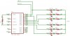
this is the schematic i used
**broken link removed**

thanks for the help.
 
hi,
Looking at the timing of the c,m,o lamps there is very little time difference.
By changing the 250K to 200K and the 100K to 150K you have probably moved the timing adjustment outside the range you want.
You could connect a 47K0 in series with 100K, make it nearer 150K.

If you have two 0.68uF caps in your scrap box, replace the 0.47uF's, this will increase the switch ON delay.

There are number of points on the circuit that could cause problems.
 
cool thats something logic i dindt think about. :) also is there any way the sequence and be restart? because i tought it was going to blink when i brake, but they only lit up and stay on. i wanted them to restart the sequence over and over, just like when i use the turn signal, dunno if that is possible with this circuit.
 
i was thinking like on a 555 timer and a cmos 4017 but i dont know how to figure out the rest of the parts i'd need.
 
You might not want to have your brake lights blinking; if it happens to confuse someone you could end up with all your lights broken (car, too).
 
mneary said:
You might not want to have your brake lights blinking; if it happens to confuse someone you could end up with all your lights broken (car, too).
Plus a nice ticket from the first cop that stops behind you.
 
They were standard on T-Birds and starting in 65 for a few years and some courgars. IIRC the original units do it with motors and wippers.

I suppose the could have made the illegal for cars not originaly equiped with them but I do not recall that ever happening.

This could be breadboarded with a microprocessor. If you used LEDs as the tail lights on the breadboard it would look somthing like this. I picked a random 18 pin chp only used 8 I/O pins.

The lines LEFT and RIGHT are inputs from the autos flasher module.

On the real circuit a voltage divider and zener would be used to get a safe 5V from LEFT and RIGHT. Replace the middle and center LEDs with transistors to drive the 12V bulbs. Voltage regulation for the processor.

Code should not be difficult.
 

Attachments

  • seqTurn.jpg
    seqTurn.jpg
    107.5 KB · Views: 2,050
Last edited:
Sequential turn signals are probably still legal in the US.

However I wouldn't be so sure about repetitive blinking brake lights.

Then again, some of the newer buses have bright red and yellow lights that flash when the brake is first applied and then go to steady red at normal brightness when the vehicle comes to a stop.
 
is there anyway i could delay the midle and outside lamp, just usisng resistors and capasitors ? or i really have to use a chip to drive it. like just putting a resistor and a capacitor betewen midle lamp and outside lamp so they lit up in sequence but with a litle delay from the inside and eachother. can i do that ?
 
If it was that easy FoMoCo would have done it int the 60's. Instead they build an expensive complex box with motors wipers and relays.

How are you going to determine when to lite the brake vrs the turn signal. With a processor you know it is the brake because power is applied to right and left at the same time.

By the time you paste enough components in to make it work you may as well have used a processor. With a processor if you goof you reprogram it.

You can buy a box on EBay that does this for about $190.
 
is there anything else i can use instead of mofset inrf9530, i have one done already and second one i only need the mofsets but nobody has it around here, is there any other i can use.
 
I have a 65 tbird that I last drove in the 80's. The car has a serious fun/cool factor. Also need serious work but has no rust.:)

Power windows, AC, cruise control, etc were normal options.
The only option I could find on mine were the hub caps. None of the above. AC is the only thing I wish I had. But the car has a unique vacuum operated vent under the rear window. If you open it and the front vents it does a very good job for a vent only system.

The signal lights use a motor/cam (not motor/wiper as I said) system. Link to ThunderBird Ranch where I found the following.

When the turn signal switch is actuated, either right or left, the circuit is completed to the flasher motor and to the flasher cam contacts. This starts the motor in operation and the cams begin to rotate. As the cams rotate, the three sets of contacts are closed in sequence and the three rear lights are illuminated in sequence beginning at the inboard light, then the center light and then the outboard light. All three lights go out at the same time and the cycle is repeated, as long as the turn signal switch is closed to indicate a turn. The front parking light bulb flashes at the same time as the center rear bulb.
 
Kleissen , does your attachment include the latest design , I am building an electric powered Eclipse and wanted the taillight setup like you have .Also I want to use five lights per side could I use pins 7 and 9 ? Or is there a better way to do this?
 
Status
Not open for further replies.

Latest threads

New Articles From Microcontroller Tips

Back
Top