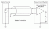
I have Lascar SP 300 digital meter (RS223-183) that normally accepts 200mv input or other inputs using scaling resistors.
The sensor has 16.7mv/psi output which I plan to buffer with op-amps and multiply by two so the full scale of the sensor output is 200mv.
The sensor and its drivers is 4 meters away from the meter and passes by some noisy equipment like alternators and generators and engines and motors etc so my first question is it OK to go with a 200mv signal maximum (typical would be 80mv) or will the signal be effected from local interference or should I raise the sensor output to say 2v full scale and then add the resistors to the meter to reduce the voltage back to 200mv?
The second question:- is it better to use the 0v as common for both sensor and meter or to use the InHgh and InLow pins.
Thanks
Q

")
