Continue to Site

Welcome to our site!

Electro Tech is an online community (with over 170,000 members) who enjoy talking about and building electronic circuits, projects and gadgets. To participate you need to register. Registration is free. Click here to register now.

  • Welcome to our site! Electro Tech is an online community (with over 170,000 members) who enjoy talking about and building electronic circuits, projects and gadgets. To participate you need to register. Registration is free. Click here to register now.

sensor and comparator

Status
Not open for further replies.

westhomas

New Member
Hello,

I'm trying to design a circuit so that a Sharp proximity sensor will trigger a 555, whose pulse is connected to the clock of a decade counter 4017.

My circuit worked fine when it was a POT/POT configuration on pin 2 and 3 of a LM 311 comparator. When the input (pin 3) went over the reference voltage (pin 2) the output would go low to pin 1 of a 555 astable. When the input went below the reference voltage, output would go high and reset the decade counter.

I realize this must be an odd configuration for a 555, but it worked...that is until I replaced one of the POT's with my sensor. I searched the datasheet for my sensor, a Sharp GP2Y0A02YK0F, but it doesn't have a comprehensive internal schematic. However, apparently there is an oscillation function...maybe this is why it isn't compatible with the 311?

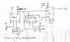
My guess though is that it's the 555 that's causing trouble. Attached is my schematic...good for a chuckle, i'm sure

thanks in advance,
wes
 

Attachments

  • sensor with 311.pdf
    1.1 MB · Views: 339
Have you measured the output of the Sharp sensor? According to the data sheet the output should vary from 0V to about 2.7Vdc depending upon it's distance from a reflective surface. If so then you should be able to adjust the pot so that it will trigger at the distance you want.

What is the pot resistance?

The oscillator is apparently just to pulse the emitter so that the sensor can discriminate between the ac signal and steady ambient light.
 
yes, the sensor is working fine...it would trigger the timer, but the 4017 and 555 were acting funny. I was using a 100K Pot, and I tried a few different values here with not much luck. I also tried buffering the sensor signal with a 337 op amp - this did nothing.

One thing i forgot to include in my schematic...there was a 10KΩ resistor across the reset of the 4017 to ground, and the resistor to +V was actually 330Ω. This configuration worked when there were two POTs but not when the sensor is on the input of the 311. I tried switching these values around and it did something, but I can't figure out what is happening.

anyway, I'm going to keep working on it...if anybody sees what is going wrong in the meantime, I would appreciate their input!

thanks for your help
 
Gating the 555 by controlling the ground pin is a bad idea. Add a transistor inverter and control the 555 reset pin, as below.
LM555 generates a nasty current spike when it switches. Add a 100uF from Vcc to GND across the 555. Also, it is good practice to add a 100nF (0.1uF) cap from Vcc to GND across each IC, as shown.
 

Attachments

  • sensor and comparator.PNG
    sensor and comparator.PNG
    522 KB · Views: 240
Yes...that works much better for the 555. thank you!

Also, I was looking at someone's schematic for a 4017 which said to tie down the reset to ground with a 10K resistor - but I moved this to the positive rail and it fixed the bug. I just hope this doesn't damage anything.

Much gratitude for helping a beginner out.
You need to connect the Reset pin to GND, either through a resistor or directly, only if you don't want to reset the counter. Your circuit shows the counter being reset by the comparator. I don't understand what you mean by
I moved this to the positive rail and it fixed the bug.
:confused:
 
Essentially I now have the circuit built according to the changes you made to the schematic - it is working fine.

The schematic I was referencing was an instruction on how to shorten the count on the 4017, by connecting the reset pin to one of the ten outputs. I gather that having a 10K resistor to ground was a way of preventing a false reset, maybe from circuit noise? It is not explained.

I'm not sure what was happening, but the 'bug' I spoke of was the that the 4017 was counting really fast when the 555 was 'off' or reset. I thought that maybe noise from the 555 was triggering this.

What I've noticed is that with the reset pin of the 4017 tied to the comparator output, as long as the resistance value is higher to ground than to +V, then it doesn't seem to interfere with the resetting.

Thanks again,
Wes
 
Status
Not open for further replies.

Latest threads

Back
Top