Continue to Site

Welcome to our site!

Electro Tech is an online community (with over 170,000 members) who enjoy talking about and building electronic circuits, projects and gadgets. To participate you need to register. Registration is free. Click here to register now.

  • Welcome to our site! Electro Tech is an online community (with over 170,000 members) who enjoy talking about and building electronic circuits, projects and gadgets. To participate you need to register. Registration is free. Click here to register now.

Self made voltage regulator doesn't work

Status
Not open for further replies.
ezesolares said:
this is a lower down schematics for this post, i will post the full schematics but for now, i think if i can't make this part work, the other dosn't matter.

The full circuit will be a digital controlled power supply with current control also.. and in the simulator everything works like a charm, but... this part, the voltage control is the most important part of the circuit.

and i put the RC network and the Cap between(28,19) but it doesn't change the actual behavior of the circuit.
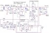
Did you try the compensation network I posted, between 1 and 28?
Are you sure the 2N3904 is not installed with the emitter and collector swapped?
 
I think you hit it on the head with the question below.
Roff said:
Are you sure the 2N3904 is not installed with the emitter and collector swapped?
 
I did tried the RC network between 1 and 28, and nothing change... (in real-life)

I always put the 2n3904 in the right way (i always check with the datasheet)..and i also swap it just to see what happened (and i can't control the output voltage now the 2n is bad connected and the output put itself to the max).

So, theres no problem over there..

Thanks

Ezequiel
 
Nigel Goodwin said:
No, they stabilise in a linear fashion - bear in mind this is an opamp wired as a comparator, not an actual comparator (which may have internal positive feedback to make it 'snap').

Hi Nigel,

Please bear with my ignorance. Here is a regulator that is called a switching regulator and uses an op-amp wired as a comparator: https://members.tripod.com/michaelgellis/power4.html

The schematic is attached. Aside from the absence of the inductor and diode, I don't see what distinguishes that design from a linear regulator. The op-amp is still switching. What other feature of the switcher design distinguishes it from a linear design (ignoring the current limiting and other extraneous features)?

Thanks. John
 

Attachments

  • power4.jpg
    power4.jpg
    50.8 KB · Views: 171
jpanhalt said:
Hi Nigel,

Please bear with my ignorance. Here is a regulator that is called a switching regulator and uses an op-amp wired as a comparator: https://members.tripod.com/michaelgellis/power4.html

The schematic is attached. Aside from the absence of the inductor and diode, I don't see what distinguishes that design from a linear regulator. The op-amp is still switching. What other feature of the switcher design distinguishes it from a linear design (ignoring the current limiting and other extraneous features)?

It's really the inductor and diode that make it a switching supply, and the supply itself is an oscillator - a linear supply shouldn't oscillate.
 
The switching power supply manage the output turning on-off the transitors, so, they charge the inductance and then, they let the diode work as freewild on the off state so the current keep flowing and so on. PWM and a control loop that manage the duty cycle so you get the output you want is the way to go (i think)

On lineal supply, the correct way of working is managing the transistor on the lineal zone, not in saturation, nor in off state...
 
shouldn't the be a zener diode and a capacitor to give a fixed voltage referance for the opamp to compare to? and use an potentiometer to vary this fixed voltage going to the opamp? that way the voltage that the opamp is compareing to won't vary if the voltage sourse drops because of the current?
 
The input voltage come directly from the source(a transform+diode+capacitor) so, the voltage won't drop no matter how much current i take (well, i could burn the transformer or the diodes :) burn baby, burn!!)

So, this is not the end design, this is just a test schematics (only the basic topology), not the end design... i must make this work so i can complete with my real design
 
Gaston said:
shouldn't the be a zener diode and a capacitor to give a fixed voltage referance for the opamp to compare to? and use an potentiometer to vary this fixed voltage going to the opamp? that way the voltage that the opamp is compareing to won't vary if the voltage sourse drops because of the current?
Yes, that's exactly what I suggested in my previous post.
The rectified DC voltage may have significant ripple. Also, it varies with the load current.
 
Nigel Goodwin said:
It's really the inductor and diode that make it a switching supply, and the supply itself is an oscillator - a linear supply shouldn't oscillate.

OK, so we have a design for a voltage regulator that is not working. The OP didn't say whether he wanted it to be a switching or linear regulator. It is missing parts to be a linear regulator, and it is also missing parts (a fewer number, actually) to be a switcher. So, it is neither, but was arguably closer to a switcher. The original design probably oscillated or was easily put into oscillation because of the high gain for UA2. I'll bet that if one had put a scope on the original design (say at the base to the 2N3904 or Darlington), you would have seen variable period, variable frequency switching by UA2.

I responded to the OP's original question, because his design was very similar to something I built a couple of months ago using a comparator. I intended my design as a switcher with a very large capacitor, but no inductor, and my results were similar to the OP's. That is, it does regulate without the inductor and diode, until you try to draw significant current from it. I even have the burned finger tips to prove what happens when I applied a real load. :D

My conclusion from that misadventure was that the inductor is necessary. That's not a novel conclusion for sure, but the experience did increase my understanding. I still don't fully appreciate why a large capacitor can't "store" the energy; whereas, it is stated that the inductor does. In my mind, I justified the inductor on the basis that it also acts as a throttle on the current being handled by the driving transistor when it turns on. As soon as I added an inductor and diode, everything cooled off, and I could draw current. It was still variable frequency and period, though, as expected.

Coming back to the OP's original post, why not just add an inductor and diode, quit messing with getting the op-amp just right for operating the 2N3904 and Darlington in their linear regions (NB, there is no current limiter on the output yet), and call it switcher?

Nigel, Thanks especially for the clarification. I spent way too much time this morning trying to figure out what I was missing in addition to the diode/inductor that was so obvious to everyone else. I truly thought he was trying to make a switcher and had not included them, just as I had tried that route.

John
 
Sorry I am late coming into this thread.

In the original schematic, the emitter of the darlingtom is 22V but its base is only 14.7V. So either the darlington is blown up or the 22V has sagged to 15.9V.

The voltage gain of the opamp is 3.2, not 2.2.
 
All the voltages i post are using a 17,4V source... sorry if i create some mistakes around... i changed from a 22V regulated source, to an unregulated 17,4 source just so i don't have to worry about the heat of the 22v regulated source (and also, the TIP would heat less)

I know i can do a minimal switching(a DC-DC) power supply, also i know i can use just a LM317.. but i want to know why this thing doesn't work, i'm on a electronic major, this is a simple circuit and it isn't working.
What could i expect from myself when i'm designing something else if i don't get this?

Otherwise, thanks for all for the help and tomorrow i will see what the osc show me :)

And.. jpanhalt, why do you said i'm lacking of a lot of elements for a lineal voltage regulator?
 
eng1 said:
Yes, that's exactly what I suggested in my previous post.
The rectified DC voltage may have significant ripple. Also, it varies with the load current.

The reference voltage won't go down because i get it from a regulated (LM7812) source, the same i use to power the opamp.
So, the unregulated part of a homemade power supply power the tip, and also power the 7812 that power the circuit (and the power supply has big capacitors to filter and also has a 100nF capaciter to filter HF).

Thanks

Ezequiel
 
if you wan't to do it with a 7812, i would use the 7812 for the reference only and draw the current for the rest of the circuit from a point before the regulator.
 
ezesolares said:
I did tried the RC network between 1 and 28, and nothing change... (in real-life)

I always put the 2n3904 in the right way (i always check with the datasheet)..and i also swap it just to see what happened (and i can't control the output voltage now the 2n is bad connected and the output put itself to the max).

So, theres no problem over there..

Thanks

Ezequiel
Did you play around with different capacitor and resistor values?

I strongly recommend you do. There must be a way to make it stable, even if it means adding a 100nF capacitor or more to the feedback loop.

Why don't you scrap the design and use an LM723 which is designed for this?
 
Status
Not open for further replies.

Latest threads

Back
Top