Continue to Site

Welcome to our site!

Electro Tech is an online community (with over 170,000 members) who enjoy talking about and building electronic circuits, projects and gadgets. To participate you need to register. Registration is free. Click here to register now.

  • Welcome to our site! Electro Tech is an online community (with over 170,000 members) who enjoy talking about and building electronic circuits, projects and gadgets. To participate you need to register. Registration is free. Click here to register now.

Self made voltage regulator doesn't work

Status
Not open for further replies.

ezesolares

New Member
Hello

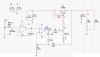
I'm trying to make a voltage regulator, and it work but under certain conditions it doesn't work as it have to.

I put my reference so i get 15V as output

At low current, i can get 15V output. (15mA)
At high current, i can only get 12V output (100mA)

I put my reference so i get 10V as output
I can get any current i want.

The IN voltage to be regulated is 17V, the opamp is powered with +-12V

I don't know where is the flaw in my "more than common" design
In the simulators (Microcap, multisim) it work ok, but in real-life it doesn't

**broken link removed**

Thank in advance

Ezequiel
PD: Sorry for my bad english
 
Last edited:
With R2=10Ω across the output you will be drawing over 1 amp of current.

Ken
 
The schematics are only to show the circuit, the load is one i tested on the simulator and forgot to erase when i posted the picture.

The R2 to get 100mA is 150ohm. (I tested a lot of dif load, the problem repeat under the circunstances i already said)

I changed the pic already
 
Try putting an inductor (100 to 300 uH) and Schottky diode (anode to ground) on the output before the sense feedback connection. That is standard practice for step-down switching regulators. See: Linear Technologies app. note 35 (there are several other app. notes as well). John
 
It's not a switching regulator, it's a linear regulator.

I'd be very surprised if it doesn't oscillate.

Q1 and Q2 are not configured as followers and will add lots of gain which is bound to give it a gain >1 with a 180° phase shift at some high frequency.

You need to place a compensation capacitor somewhere in the feedback loop. I'd start off with 10nF between node 28 and 19, then try larger and smaller values.
 
Its linear, not switching... the opamp has a negative feedback (control loop).

(And i use a capacitor in the feedback loop (in the 22K) but i took it off from the schematics for the sake of simplicity)

And i don't get the idea of Q1 and Q2 as followers, they are not followers, they are commanded by the opamp (with control the current that goes to Q1 and then, goes to Q2)

Thanks in advance

Ezequiel
 
Have you looked at points 2, 8, 9, or 16 with a scope? What do you see?

John
 
I don't have an scope, i'm a south american student and here, the osc are very expensives.. but i can check on my faculty lab on tuesday.

I changed R6 to 270ohm.

All this i check with my multimeter (an UNI-T UT70A) with one of the probes to ground.

I change the Vin to 17,5 (another non-regulated voltage source)

Putting the Vref as 10V, i won't get 22V, and i get 15,6V (which seems to be the max i can get as output)
point8(p8) = 14.7
point2(p2) = 0,2
point9(p9) = 11,1V <-- opamp is saturated to 12V (V+)
point16(p16) = 0,9V

Now, all the test i'm describing next, the voltage ref is 14,4 and i change the load

With no load and i get almost the same with R2=4700ohm (Vout = 14,4V)
p8 = 16,7V
p2 = 16,6V
p9 = -1,4V (???) <-- trying to regulate down?
p16 = -1,6V

With 100ohm as load (Vout = 14,2V)
p8 = 13,9
p2 = 5,1 - 5,3
p9 = 5,83
p16 = -1,0

with 31ohm as load (Vout = 12,7)
p8 = 12V
p2 = 0,13V
p9 = 11,15 <--opamp saturated
p16 = 0,86V

Tuesday i'm going to get an osc on my hand and i will check it..

thanks in advance

i don't get anything more...

Ezequiel
 
Last edited:
You have much more loop gain than you need, combined with multiple poles that are causing oscillation. I played with your circuit on LTspice and empirically came up with the modifications below. Simulation doesn't always correspond to the real world. Give it a try and let us know how it works.
EDIT: You should be able to get at least 20V out with a solid 22V unregulated source (if it has ripple, it must stay at least 2v above the desired output voltage). Keep in mind that your gain is 3.2, so the reference will need to be 6.25V for a 20V output.
 

Attachments

  • ezsolares pwr supply.PNG
    ezsolares pwr supply.PNG
    249.1 KB · Views: 190
Last edited:
Its almost the same. i get 12,78V with a load of 34ohm.
So, the circuit in real life keeps behaving the same :(

DAMN REAL-LIFE!! :p

Where can i learn who to calculate how much poles and zeros i have in a design like this? (a book, anything). I really don't know how to do it, i'm in a 3er year of electronic eng.

I'm asking help because i run out of ideas and i don't know where the prob is... really don't know.

And in my real design(tested only on the simulator) i already have the capacitor and the resistence between V- and Output of the opamp, also i have a capacitor between the TIP105 output and the V+ of the opamp.. gain a lot of stability with them. (but i take it out for now for the sake of simplicity)

Thanks for all the help

Ezequiel
 
You mention Vref. What voltage are you referring to?
EDIT: Do you have compensation on the NE5534? It is not stable below gain=3. You don't even need that op amp. The input impedance of the NE5532 is very high.
 
Last edited:
jpanhalt said:
UA2 looked like a switch to me. John

As everyone else has said, it's linear, UA2 is an opamp connected as a comparator - and like everyone else has said, it won't work because it's lacking in capacitors to keep it stable.
 
As Roff said, you don't need the first amplifier. I would use a reference IC to provide a stable voltage reference for the NE5532; otherwise, any change of the input voltage would be amplified at the output, resulting in poor regulation.
That said, I've always used an NPN device as the pass transistor for that topology.
 
Nigel Goodwin said:
As everyone else has said, it's linear, UA2 is an opamp connected as a comparator - and like everyone else has said, it won't work because it's lacking in capacitors to keep it stable.

Without some changes, isn't UA2 going to drive to either extreme? If and when that happens, it will do the same downstream. Thus, it will act like a switch. Frequency and pulse width will be variable. John
 
jpanhalt said:
Without some changes, isn't UA2 going to drive to either extreme? If and when that happens, it will do the same downstream. Thus, it will act like a switch. Frequency and pulse width will be variable. John

No, they stabilise in a linear fashion - bear in mind this is an opamp wired as a comparator, not an actual comparator (which may have internal positive feedback to make it 'snap').
 
Thanks. I obviously need to study that aspect more. I understood they could be connected like comparators. I didn't understand the nuances of them not acting like ones. John
 
First, i added the follower for the voltage reference(represented by the potentiometer) just to be sure i don't have a problem there.

Well, here is the new schmatics that doesn't work also in real life, i change some stuff from the feedback i got here.
I changed the opamp for an op07, i added more gain (9,1) and really nothing else.. it doesn't work either.

**broken link removed**

But the thing that keeps me looking strange is..
i put the voltage refence so i get 14V as output
1 - with no load, i get 14V
2 - i put some load, i get 13V
3 - i put more load, i get 12,4V
4 - i put even more load, i still get 12,4V
5 - Getting more than 700mA, i still get 12,4V

So, why could it be? The output voltage goes down with current but it stay at 12,4V no matter how much current i try to get it out... (obviouslythe correct voltage output should be 14V)

Its like the circuit get stable at that point? (the opamp input voltage are +-12V) also, at that point the opamp get saturated..

I'm still waiting for tomorrow so i can see with an osc how the circuit works

Thanks in advance

Ezequiel
 
If you have loop compensation (the RC network that I drew), why don't you have it on your schematic?
 
this is a lower down schematics for this post, i will post the full schematics but for now, i think if i can't make this part work, the other dosn't matter.

The full circuit will be a digital controlled power supply with current control also.. and in the simulator everything works like a charm, but... this part, the voltage control is the most important part of the circuit.

and i put the RC network and the Cap between(28,19) but it doesn't change the actual behavior of the circuit.
 
Status
Not open for further replies.

Latest threads

New Articles From Microcontroller Tips

Back
Top