Continue to Site

Welcome to our site!

Electro Tech is an online community (with over 170,000 members) who enjoy talking about and building electronic circuits, projects and gadgets. To participate you need to register. Registration is free. Click here to register now.

  • Welcome to our site! Electro Tech is an online community (with over 170,000 members) who enjoy talking about and building electronic circuits, projects and gadgets. To participate you need to register. Registration is free. Click here to register now.

SCR's (phase angle control?)

Status
Not open for further replies.

wesdu

New Member
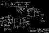
Can someone help me with the circuit to control for two of SCR’s of which I like to use to regulate voltage of the heater? …I was searching internet, some called it “phase angle control” they mention using two SCR’s, but there was not much about, how to precisely fire the gate of the SCR’s to cut portion of the AC sin-wave. Thanks.
 

Attachments

  • scr_control.pdf
    9.8 KB · Views: 1,778
I believe a "phase angle controller" is what you want. I built one for my tesla coil awhile back. I attached the schematic that I used. It's actually Steve Connor's design, Tesla Four - system diagram

If I remember right, It uses two 2n3904 transistors to sync the first 555 timer to the zero crossing of the AC signal. The pot (labeled firing angle control) delays the SCR for an adjustable amount of time. (so setting the pot for a 4.16 ms delay will cause the SCRs to fire half way through the cycle). The 91k resistor might have to change for it to run properly at 60Hz.

The 2nd 555 timer generates a series of short pulses which are sent to the SCRs.
 

Attachments

  • phasecontrollerblk.jpg
    phasecontrollerblk.jpg
    56.1 KB · Views: 1,585
Thanks for advice, the truth is I’m trying to make my circuit as simple as possible.
Jrz126, why would I need the second timer, my understanding was that SCR,s ones open stays open till zero crossing, so what are those extra short pulses for?
Another question is do I need pulse transformer? …can I just go straight from the timer #1 to some sort of opt-coupler which would control the SCR’s?

Thanks, wd
 
Jrz126, why would I need the second timer, my understanding was that SCR,s ones open stays open till zero crossing, so what are those extra short pulses for?
Another question is do I need pulse transformer? …can I just go straight from the timer #1 to some sort of opt-coupler which would control the SCR’s?
The extra pulses are needed when driving an inductive load. If only one pulse was sent, its possible the SCR would not turn on.

You need to send it a short pulse (or series of pulses) or you will burn up the gate. Acording to this datasheet: https://www.electro-tech-online.com/custompdfs/2009/02/L073.pdf this SCR can only handle 0.5W of average power on the gate (see Pgav).

The pulse transformer is the easiest method. I think you would need a seperate isolated powersupply for each SCR gate. Also, referring to the SCR I mentioned above, the gate needs atleast 100mA to turn on. most optoisolators arent powerful enough.
 
Hi ,
Could u please help with any logical ckt , inorder to built a SCR firing ckt ,
Since i was trying to use a PLC inorder to accept the thermocouple readings from the furnace location and use a PID algorithim to indirectly fir the SCR gate from teh Digital o/p cards ,\ Please need some info could u please send a attachment via mail on my email Id;
iee_engineers@rediffmail.com
 
--------------------------------------------------------------------------------

Hi ,
Could u please help with any logical ckt , inorder to built a SCR firing ckt ,
Since i was trying to use a PLC inorder to accept the thermocouple readings from the furnace location and use a PID algorithim to indirectly fir the SCR gate from teh Digital o/p cards ,\ Please need some info could u please send a attachment via mail on my email Id;
iee_engineers@rediffmail.com
 
Status
Not open for further replies.

Latest threads

New Articles From Microcontroller Tips

Back
Top