Continue to Site

Welcome to our site!

Electro Tech is an online community (with over 170,000 members) who enjoy talking about and building electronic circuits, projects and gadgets. To participate you need to register. Registration is free. Click here to register now.

  • Welcome to our site! Electro Tech is an online community (with over 170,000 members) who enjoy talking about and building electronic circuits, projects and gadgets. To participate you need to register. Registration is free. Click here to register now.

schmitt trigger

Status
Not open for further replies.

ghie ghie

New Member
Newbie here! :) Can someone help me to simulate schmitt trigger circuit in LT Spice IV? And I also need to have a stick diagram of it on L-Edit. I'm new with those applications, I have tried to search for it but still I can't get how to do such thing and I haven't seen an exact schematic diagram of schmitt trigger like what I saw in...

Circuit Design, Layout, and Simulation
Third Edition
R. Jacob Baker

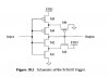
I attached a photo of the schematic diagram here..
Please help me...:arghh::arghh::arghh:
 

Attachments

  • OPERATION1.jpg
    OPERATION1.jpg
    29.1 KB · Views: 826
This is a good example of a Schmidt Trigger circuit done in LtSpice. Before worrying about just drawing a circuit off the internet it is important to understand what a schmidt trigger is and how it works. I suggest you start with the basic theory and then apply it to the linked circuit. Never used L-Edit so you are on your own with that.

Ron
 
I'll show you how to use LTSpice to analyze a Schmitt trigger; not how to build one out of CMOS elements.

First, consider the following noisy input, V(in). It is a slow ramp with a sinusoidal noise riding on it. I feed it to three cascaded CMOS inverters, and plot the voltage at V(out1), V(out2), and V(out3). Even though each inverter adds gain, that does square the edges, but it doesn't get rid of the multiple edges caused by the amplified noise source...

284.gif

Compare the plot above to the one below where I added positive feedback from the second inverter V(out2) (which is in step with the input signal) to the input. R1 and R2 form a voltage divider, so the feedback signal is about 20% of the output step of 3V. Note that eliminates the multiple edges.

Furthermore, look at the two cursors I placed on V(in). Note that up-going trip point is about 261mV higher than the down-going trip point, meaning that the circuit now has hysteresis, which provides the ability to discriminate against the ~100mV of noise riding on the ramp.

284s.gif

This is how a Schmitt Trigger works. I was able to simulate its behavior in LTSpice, and show its salient points. Your job is to get correct NMOS and PMOS models (ones that have channel length and channel width parameters) for the specific CMOS process you are designing for, and to find a way to make a Schmitt Trigger that doesn't utilize 100K resistors...
 
Status
Not open for further replies.

Latest threads

New Articles From Microcontroller Tips

Back
Top