Continue to Site

Welcome to our site!

Electro Tech is an online community (with over 170,000 members) who enjoy talking about and building electronic circuits, projects and gadgets. To participate you need to register. Registration is free. Click here to register now.

  • Welcome to our site! Electro Tech is an online community (with over 170,000 members) who enjoy talking about and building electronic circuits, projects and gadgets. To participate you need to register. Registration is free. Click here to register now.

Schematic conventions

Status
Not open for further replies.
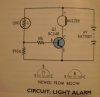
Here's a schematic of a light-detection circuit. When light is shone on the circuit, it buzzes.

Having a look at this schematic, it seems most natural to me that the schematic should be drawn so that the LDR and the 390 should be on the middle 'branch' and the transistor and the buzzer should be on the leftmost 'branch'. The transistor stands in the way of the battery operating the buzzer.

Can schematics be drawn either way, or is there some sort of convention that I should know about?

Richard
 
Schematic is here

Forgot attachment
 

Attachments

  • P1220003.JPG
    P1220003.JPG
    151.7 KB · Views: 180
Typically schematics in the US (I'm not sure about the rest of the world) are drawn with the signal flow more or less left to right. Thus the signal starts with the LDR and resistor on the left, and then goes to the transistor and buzzer on the right. The circuit power source can be shown anywhere.

But that's just general convention. Sometimes with large schematics it may start out at the top left to right, loop at the right end, and come back right to left.
 
The LDR controls the base current of the transistor, which amplifies the base current to control the buzzer. The circuit is drawn conventionally, so that the logical signal flow is from left to right. That is the way I would have drawn it...
 
Status
Not open for further replies.

New Articles From Microcontroller Tips

Back
Top