Continue to Site

Welcome to our site!

Electro Tech is an online community (with over 170,000 members) who enjoy talking about and building electronic circuits, projects and gadgets. To participate you need to register. Registration is free. Click here to register now.

  • Welcome to our site! Electro Tech is an online community (with over 170,000 members) who enjoy talking about and building electronic circuits, projects and gadgets. To participate you need to register. Registration is free. Click here to register now.

Scalextric Lap Counter Help

Status
Not open for further replies.

alexb1406

Member
Ok, I'm a big boy now but I refuse to grow up! Who's with me on this one?

I've recently found a renewed interest in my old Scalextrics going back to the 60's and 70's and I'm trying to improve the performance of a particular lap counter that I always favoured. It is an electric one where there is a short section of track (about 8 inches length) that is separated from the rest of the circuit and when the car goes over this section the circuit to a solenoid is completed and triggers the lap counter. There are a few problems though in that it relies on good continuity between the pick up braids and track, but this is rarely the case so the result is either multiple triggers as the car goes over the section, or if the car is too quick no trigger at all! Also, as the section is separated from the rest of the track and the motor and solenoid are connected in series as the car geos over, there is little power remaining to drive the car and unless it has some momentum before it gets there it sometimes stops.

I had a bright idea to use that section to trigger a monostable to activate the solenoid, so once triggered it would not re-trigger until the monostable had completed its cycle, by which time the car would be clear of the lap counter section. This would get around the problem of bad contact between braids and track, which it does perfectly.

However, all is not well as it often triggers as the car is driven around the rest of the track, usually on throttle opening, and more so with later more powerful cars.

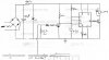
I've attached my circuit diagram using a 555 timer. As the car goes over the lap counter section power is applied to it via the 8.2Ω resistor, and it is the voltage drop across this resistor that triggers the timer. This way plenty of power is applied to the car over this section. I would have preferred to make it controllable with the throttle but can't think of a way to do it.

However, the main thing I would like to sort out is this false triggering. I have also tried connecting a 100nf cap in series between the BC547 and pin 2 input on the 555 but this has had no effect. The only way I can get around the problem is to connect the lap counters to a separate power supply.
 

Attachments

  • Scaletric Lap Counter159.jpg
    Scaletric Lap Counter159.jpg
    34.5 KB · Views: 210
Incidentally I forgot to say the bridge rectifier is only there as a protection in case of reverse polarity as the leads, although marked, could be connected the wrong way round.
 
I think the supply voltage to the 555 is being pulled low and causing re-triggering. Try increasing the 100uF cap to 1000uF and/or adding a 100uF cap across the zener.
 
1000uf - that's huge!!! I did wonder if that could be the problem but thought 100uf would be enough. Have to go shopping for it later in the week.

I just realised I made a mistake in the diagram - the solenoid +ve is connected to the 12v supply before the zener so it would get the full 12v, but I don't think that makes any difference.
 
I agree with Alec - put a big electrolytic across that zener.
 
Ok, thanks. Do you mean 1000uf after the 680Ω resistor? The way I read Alec's post was either 1000uf instead of the 100uf (before the resistor), and/or 100uf across the zener after the resistor.
 
By "big" I mean at least 100 uf. You can get by using a smaller one after the resistor because the resistor increases the filter's RC time constant. Alec's suggestion of 1000 uf is not overkill - from your description, and that 8.2 ohm resistor to ground on the sensing input (nice low value, not likely to pick up noise), it seems the noise must be getting in on the 12V line.

Was that solenoid originally designed to go in series with the car's motor? If so, it might be a good idea to add a series resistance - but you did the right thing hooking it ahead of the 680 ohm resistor, that helps keep noise out of the timer circuit.
 
So would I get away with just moving the 100uf after the 680 resistor? It would save me having to go out in search of a 1000uf cap that I don't have here at home.

And yes, the solenoid initially was connected in series with the motor - I'm trying to remember why I chose to connect it ahead of the 680 resistor (this is a project I started many months ago), I think it must have been to give it the full 12v supply (the zener is 10v) and drawing nearly 200mA I would need a fairly hefty zener and resistor to cope. The power supply varies up to 20+ volts, especially with the bridge rectifier (don't understand why the rectifier increses the voltage), depending on load.
 
Last edited:
You might get away with that - try it, should give some improvement. Really could use more filtering, though. Even a 220 uf or 330 uf would help - practically any old busted piece of electronics will have something you could use.

The voltage increases because the 12V rating on the transformer is the RMS value (a sort of "average"), the peak voltage (at the top of the sine wave) is considerably higher. Without much of a load, the voltage will float right up to that peak value.

The fact that the solenoid was originally in series with the motor means it doesn't need the full 12V, and is being overdriven. For the fraction of a second the 555 operates it probably won't cause a problem, but it would be nice to put a resistor in there and knock down the current some. With a blind guess, I would say if you have another one of those 8.2 ohm resistors, try that. Need to know the resistance of the solenoid to figure it better.
 
Ok, I'll try that first - see what happens.

The voltage from the transformer is already rectified - I have included the rectifier in my circuit as a protection in case the leads from the lapcounter are connected the wrong way - I've marked them but could still be connected wrong if I'm not paying attention (or someone else does it!). The lap counter I think will still work but the car will reverse quite fast as it hits the track section.

Solenoid resistance is quite low at around 55Ω so it would draw close to 200mA - however I'm not sure whether the BC639 that switches it is driven fully to saturation (is that the correct term?) as at first I used a 4.7K resistor to the base, but had to reduce it to 2.2K as it didn't always switch the solenoid on. I'd need to check it again but I don't think the voltage to the solenoid drops fully to 0v.

Anyway, I'll try moving that cap tomorrow - I'll let you know if it works - thank you so far for your help!
 
Good doing that with a separate bridge, it will help keep drops on the car side from pulling down the 555's supply, and isolate the filter cap from affecting the cars.

The voltage from the transformer is rectified, but not filtered. If you open the "power base", the biggest cap in there isn't much more than .1uf. They don't put an appreciable filter cap on slot car tracks, and when you add one, you see that peak voltage. The Scalextric isn't so bad at 12V, the popular slot car tracks here go clear up to 40V when you filter them!
 
Doesn't 40v burn the motor out!?!

My setup is pre-"power base" - I have various transformers but the one I'm using at the moment for this is the original "Smoothflow" dating back to the 60's. I like it as it has a push-button cut-out that can be instantly reset. Later ones had to wait a few minutes while the thermal trip reset itself.

Ok, I tried moving the cap after the 680 resistor but if anything it made it worse! I then tried adding a couple of spare 100uf caps in parallel with the original one (300uf total) and it made no noticeable difference. Then I removed the two additional caps and placed one ahead of the rectifier - I don't know why but this seems to have cured it! Yeah!!!

Problem now is the only bipolar 100uf cap I can get is physically too big in size to fit in the space available - ideally I would choose a bigger cap. The reason I want a bipolar is in case it is connected wrongly, remembering now it is ahead of the rectifier. I know electrolytics don't like reverse polarity, but would one be likely to survive as it won't be connected like that for long - only until someone drives a car around the track and finds out it goes backwards on the lapcounter! Or maybe I could place a diode in series; would that work?
 
Diode in series sounds like a fine way to do it. Cars probably won't notice the .7V drop because with that filtered supply, you get less reactance from the car's windings. Heck - might even run a little faster.

The 40V issue has to do with cheap transformers that are overwound to compensate for high internal resistance.
 
No, the cars supply comes before the filtering so they won't see the .7v drop.

You've got me thinking now - maybe I should filter the supply...

Or maybe I should get back to what I'm supposed to be doing today...work....
 
Colin, thank you but I know! I did say somewhere that I made a mistake when I was drawing the diagram - the supply for the load comes before the 680 line resistor. It was originally placed there before I decided to use a zener to control the voltage with the resistor.
 
I don't understand what you mean - are you referring to the 100K resistor between collector and 10v supply? Can you suggest what would be better?
 
The diagram shows a transistor that is turned on via a diode on the base.
This is a BAD design. The transistor is said to be in a HIGH IMPEDANCE STATE.
This means the base is FLOATING.
When the input is LOW, the diode does not deliver any voltage to the base and the effective resistance on the base is infinite. What we mean by this is the diode provides no resistance (an infinite resistance) and any noise picked up by the base will turn the transistor ON. To prevent this from happening, a 100k resistor is connected between base and 0v rail.

**broken link removed**
 
Last edited:
Ok, I've just googled "high impedance state" and I can't see what you are referring to. The first transistor (BC547) has emitter to ground, collector to 10v via the 100K, and base to ground via the 8.2ohm resistor. The output transistor (BC639) has emitter to ground, collector to 12v via the solenoid and base to the output of the 555 which is either low or high depending on the input.
 
Status
Not open for further replies.

New Articles From Microcontroller Tips

Back
Top