Electro Tech is an online community (with over 170,000 members) who enjoy talking about and building electronic circuits, projects and gadgets. To participate you need to register. Registration is free. Click here to register now.
Welcome to our site! Electro Tech is an online community (with over 170,000 members) who enjoy talking about and building electronic circuits, projects and gadgets. To participate you need to register. Registration is free. Click here to register now.
A 5V supply to an LM358 results in 3.7V max saturation output for my non-inverting amplifier. I'd like it to be 5V max output to maximize my output range to my uC, so I suppose adjusting the supply voltage helps that?
Wait a mo... rail-to-rail is only inherent to specific op-amps, eh?
All devices are "commoned" in my circuit, and some is restricted to a supply of max 5.25V. I suppose since I'll be using a 6.7V supply, dropping the voltage to the limited-voltage device using diodes will aid this?
Lastly, AG, you said in a another post that a 0.2V (200mV) schottky diode is needed to limit the voltage spike between the two inputs so that the op-amp doesn't get damaged. I found out that LM35's output is 300mV as an input to the non-inv input to the LM358 (in room temp), and the op-amps responded normally. Can you please explain this?
A Schottky diode at an input of an LM358 to ground will limit its negative voltage to 0.2V so that the input is not destroyed by a high current that flows when it is -0.3V or more.
The max allowed differential voltage (between inputs) is 32V regardless of the amount of supply voltage.
The inputs work fine all the way down to 0V.
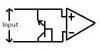
Your transistor will not saturate with its base connected to its collector. It is just a 0.65V silicon diode. The diode will have avalanche breakdown at about 6V to 7V when the polarity is reversed.
Why don't you post your entire schematic for us to see if input protection is required?
It's from a previous post you answered, a piezo disdrometer connected to the opamp.
On the other hand, I tested my TIP41C, diode-connected and my DMM read 0.193 V in the diode reader mode. I suppose I've just re-invented the schottky diode?
A disdrometer is........ googled.
Are we in the same tune here? I'm referring to protection diodes across input for the op-amps. the details you mentioned is impertinent to the... jump three posts backwards, I'm afraid.
This site uses cookies to help personalise content, tailor your experience and to keep you logged in if you register.
By continuing to use this site, you are consenting to our use of cookies.