Continue to Site

Welcome to our site!

Electro Tech is an online community (with over 170,000 members) who enjoy talking about and building electronic circuits, projects and gadgets. To participate you need to register. Registration is free. Click here to register now.

  • Welcome to our site! Electro Tech is an online community (with over 170,000 members) who enjoy talking about and building electronic circuits, projects and gadgets. To participate you need to register. Registration is free. Click here to register now.

Sallen key filter and treble boost filter

Status
Not open for further replies.

elnino86

New Member
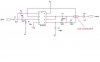
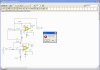
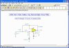
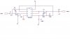
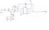
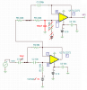
Hye all, here are my shcematic.Both of them doesnt work properly on the breadboard.I didnt see anything wrong with both of it.I conduct the experiment with audio generator as a input signal.The amplitude is set at 10mV.The first test is on the sallen key filter and 2nd is on the treble boost.Both of the circuit were test separately.

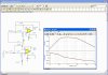
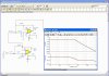
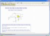
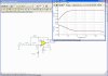
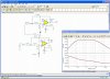
I put in a audio signal from audio generator and see the output on the scope.I started to increase the frequency and suppose the sallen key filter using TLC2272 will alter the signal above 3kHz.But the signal still appear at the output even i increase until 10kHz.

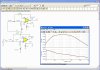
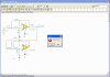
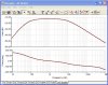
Same goes with my treble boost filter.It suppose increase the gain at the break frequency 10kHZ as i increase the gain from 100Hz but nothing happen as i observe the output at the scope.

At the first sight,there is nothing wrong with my circuit design.Theoretically,it will work as plan.May anyone comments on my circuit?
 

Attachments

  • sallen key band pass filter(human speech).JPG
    sallen key band pass filter(human speech).JPG
    16.2 KB · Views: 512
  • treble boost using TL071.jpg
    treble boost using TL071.jpg
    16 KB · Views: 589
10mv isn't much of an input signal - the maximum offset voltage on that TL071 in the treble boost circuit is almost that high to begin with, and the Sallen-Key doesn't really amplify. Give it a bigger input, couple of volts peak-to-peak, and see how they respond.
 
Last edited:
Your circuit is connected wrong??

Your first circuit (sallen key) has the input connected to output??
Try downloading TINA 7.0 (free) and simulate your filters
pin 1 is output
 

Attachments

  • Capture.jpg
    Capture.jpg
    334.2 KB · Views: 290
oups I mis read your schematic

Download TINA 7.0 anyway. It couldn't hurt and you might learn something. I know I have since using it.
 
hope this is your circuit

yep it dosn't work
 

Attachments

  • Capture.jpg
    Capture.jpg
    328.5 KB · Views: 264
remove c5

kept comming up illregular circuit with c5 in circuit
 

Attachments

  • Capture.jpg
    Capture.jpg
    334.4 KB · Views: 279
heres your circuit with out c5

removed c5 and circuit works kinda
needs tweeking for a sharper response??
 

Attachments

  • Capture21-30-2009-9.41.33 PM.jpg
    Capture21-30-2009-9.41.33 PM.jpg
    88.1 KB · Views: 186
full screen shot

oups only got partial shot
 

Attachments

  • Capture21-30-2009-9.44.06 PM.jpg
    Capture21-30-2009-9.44.06 PM.jpg
    328.3 KB · Views: 244
I think you should review the design of Sallen and Key filters. You messed them up.

Can you turn off the dots in your schematic drawing software?
 

Attachments

  • filters.PNG
    filters.PNG
    121.2 KB · Views: 230
10mv isn't much of an input signal - the maximum offset voltage on that TL071 in the treble boost circuit is almost that high to begin... Give it a bigger input, couple of volts peak-to-peak, and see how they respond.

Im already increase it to 1V p-p.Still the same output.It not increase the gain at break frequency.I leave the offset floating.Do i need to ground it?If im ground it,it will bypass the 1080Ω right?

the Sallen-Key doesn't really amplify

I set the sallen key in unity gain.
 
yep it dosn't work

Hai Mr.DEB,thanks for trying to simulate it for me.:)

I think you had misunderstanding on my circuit.Actually i didnt connect pin 2 with pin 7.It directly go to pin 5 as you can see clearly in my early post.:)

Im sorry for any inconvenience.
 

Attachments

  • sallen key band pass filter(human speech)2.JPG
    sallen key band pass filter(human speech)2.JPG
    17.2 KB · Views: 208
I rewired and still dosn't work w/ cap

I rewired as per schematic with and without C5.
Dosn't work with C5
 

Attachments

  • Capture21-31-2009-5.18.02 AM.jpg
    Capture21-31-2009-5.18.02 AM.jpg
    327.5 KB · Views: 178
  • Capture21-31-2009-5.19.17 AM.jpg
    Capture21-31-2009-5.19.17 AM.jpg
    327.1 KB · Views: 171
hi Mr Deb,
you have copied the messed-up lowpass filter.
 

Attachments

  • 2nd-order lowpass filter.PNG
    2nd-order lowpass filter.PNG
    56.3 KB · Views: 221
kept comming up illregular circuit with c5 in circuit

Hai Mr.Deb, the C5 actually connect to the pin 7 as a coupling capacitor and not connected pin 5 as you draw.Im sorry again for any misunderstanding at my previous schematic.

As my early post,why does my treble boost filter doesnt work properly?At low frequency,it will give gain about 2 and will increase at 200 gain at break frequency,10kHz.
 
Last edited:
Download TINA 7.0 anyway. It couldn't hurt and you might learn something. I know I have since using it.

Hai,thanks.Thanks for sharing some good info.I will download it.Im still busy on fixing some circuit.Hopefully this software will help me out.Sometime we has a perfect result at the simulation,but its not work well on the breadboard.:(
 
You can float the offsets, that's not the problem. When you increased the input to 1Vp-p, did the output increase? Are the outputs of the amps at a +4Vdc offset?
 
with and without offset battery

circuit with the offset battery then as per audiguru with out the battery
not real sure which is better for desired results
 

Attachments

  • Capture21-31-2009-1.23.59 PM.jpg
    Capture21-31-2009-1.23.59 PM.jpg
    332.8 KB · Views: 165
  • Capture21-31-2009-1.23.17 PM.jpg
    Capture21-31-2009-1.23.17 PM.jpg
    327.8 KB · Views: 165
Mr DEB,
Please learn about how opamps and Sallen and Key filters work and are made.
 

Attachments

  • filters again.PNG
    filters again.PNG
    111.1 KB · Views: 220
Deb, you never leave either of the inputs on a regular opamp just hooked to caps like that. They will float all around and the output can go anywhere.
 
All I did was draw out the orginal circuit posted

on this thread.
not recomending any particular form of connections.
I did find that the orginal post had a cap on the output whitch I found using TINA that its an irreguar circuit.
What I don't understand is why the battery in a sallen key but audioguru says to take it out?
Advantages of Saleen key vers ??
 

Attachments

  • Capture21-31-2009-6.33.39 PM.jpg
    Capture21-31-2009-6.33.39 PM.jpg
    205.2 KB · Views: 155
Status
Not open for further replies.

Latest threads

Back
Top