Continue to Site

Welcome to our site!

Electro Tech is an online community (with over 170,000 members) who enjoy talking about and building electronic circuits, projects and gadgets. To participate you need to register. Registration is free. Click here to register now.

  • Welcome to our site! Electro Tech is an online community (with over 170,000 members) who enjoy talking about and building electronic circuits, projects and gadgets. To participate you need to register. Registration is free. Click here to register now.

RTCC battery backup w/sleep

Status
Not open for further replies.

cyrusthevirus

New Member
My project is an aquarium control system. A 5V power supply supplies a 5V LCD and then is reduced down to 3.3V to supply the PIC24F. The PIC uses 8 PWM channels to simulate a sunrise/sunset. In addition I am using 4 ADC channels to measure pH, temp, ORP and salinity. I output these values as well at the current date/time to the LCD.

All of the above is working very well. I am looking for something to maintain the RTCC if the power goes out. I do not need to run the LCD or any other features. I just do not want to lose the clock.

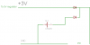
I searched online and from what I can tell is to use a CR2032 as a battery backup with a schottky diode.

Does anyone have a circuit they could share? Anyone have code they could share for putting the PIC into and out of sleep?
 
How is your RTC implemented? Depending on the answer you may need low power mode rather than sleep.

Would it be easier to use something like this.

Mike.
 
I don't think a low power mode is an option, since he is worried about the power source going out.

I agree with mike, instead of using on board RTCC, use the ds1307 and attach battery to that.
 
Would be interesting to see your project. Working on something similiar for an office nano tank.

My project is an aquarium control system. A 5V power supply supplies a 5V LCD and then is reduced down to 3.3V to supply the PIC24F. The PIC uses 8 PWM channels to simulate a sunrise/sunset. In addition I am using 4 ADC channels to measure pH, temp, ORP and salinity. I output these values as well at the current date/time to the LCD.
 
My latest diagram is outdated, so let me see if I can throw something together. I was hoping to not have to recreate my project and was looking for a solution to reduce the power consumption. Is there a way to see how much power the pic consumes and have bettery that covers that consumption for 24 hours? I would also need a way to disable the LCD.
 
Bypass the 5V regulator, feed 3V directly to the pic from your back-up battery. Provide a means for the PIC to sense the absence of the 5V (voltage divider to digital input pin?). Modify the code to go into a "power saving" mode whenever the 5V is missing.

Another approach is to save all of the critical parameters to flash, and simply restore them upon wake-up, combined with the external timekeeper.
 
Last edited:
In sleep mode, the 12F and 16F PICs draw ~2ua, so you could keep them alive for months. If all you have to to do is wake up ~ once per second, do something that takes 1msec (increment your time counter) , and then go back to sleep, it would still only be an average power draw of <<1mA. Another approach is have a 32kHz watch crystal oscillator as your instruction clock, in which case the power draw is also reduced by a factor of 100 to 1000 compared to clocking at 8MHz.
 
Yes, when in sleep mode the PWM will stop. To wake up the PIC from sleep you need to configure it to awaits an interrupt (for example the watchdog timer after 2 seconds)
 
I am running 4 ADC channels and PWM on the PIC. IF I sleep the pic, the PWM would stop correct?

If the AC fails, why do you need to run anything other than keeping time? Who cares what the ADC readings are if you cannot do anything about it, like run a heater, and airpump, etc?
 
If the AC fails, why do you need to run anything other than keeping time? Who cares what the ADC readings are if you cannot do anything about it, like run a heater, and airpump, etc?
You are correct. I do not care about anything, but the clock. However I was confused by:

Bypass the 5V regulator, feed 3V directly to the pic from your back-up battery. Provide a means for the PIC to sense the absence of the 5V (voltage divider to digital input pin?). Modify the code to go into a "power saving" mode whenever the 5V is missing.

How is the PIC powered when the power is up? By the battery? If not how do I prevent the battery from back feeding to the 5V LCD?
 
Two Schottky diodes?
 

Attachments

  • battery.png
    battery.png
    2.4 KB · Views: 293
Any low-current Schottkys. PIV only needs to a few volts. Max current is < ~50mA. If you want 3.3V at the PIC VDD pin during AC operation, your intermediate regulator should put out ~3.7V. A 3V battery minus the 0.3V diode drop will run the PIC, although you might want to read the data sheet about what happens with VDD=~2.7V.
 
Are both Schottkys the same size? What is PIV? Also so I understand, the Schottky diode only lets voltage travel in one direction. Also because the voltage from the AC is higher than from the battery, the diode does not pass any voltage to the circuit. Is that correct? Will the diode leak any voltage?
 
Status
Not open for further replies.

Latest threads

Back
Top