Continue to Site

Welcome to our site!

Electro Tech is an online community (with over 170,000 members) who enjoy talking about and building electronic circuits, projects and gadgets. To participate you need to register. Registration is free. Click here to register now.

  • Welcome to our site! Electro Tech is an online community (with over 170,000 members) who enjoy talking about and building electronic circuits, projects and gadgets. To participate you need to register. Registration is free. Click here to register now.

RS485 network power question

Status
Not open for further replies.

3v0

Coop Build Coordinator
Forum Supporter
I would like to provide two sources of power to a RS485 network and am not sure I have it right.

The physical network cable will consist of A, B, GND, and V+. The supply for V+ needs to be large enough to power the entire network.

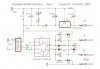
Each RS485 interface regulates V+ to +5. Most nodes are powered by V+ using this regulator. Critical nodes will also have a small local regulated power supply, maybe 100mA.

D1 (1N4001) prevents the small local supplies from attempting to power the entire network.

Since the uC and the V+ powered regulator are both regulated to +5V there should be no problems having the two supplies? Or should I make sure that the output of the interface regulator is always a bit less then that of the uC regulator?

3v0
 

Attachments

  • RS485-sch.jpg
    RS485-sch.jpg
    42.8 KB · Views: 216
Last edited:
You have 4.5 volts going to supply the micro (because of D1).
I would move D1 to the RS485-1 connector. (input to the regulator not output)
 
I would add a diode as I have shown in my modified version of your circuit. This diode prevents a dead local PSU from loading the 485 bus PSU.

However, I cant help but think that your philosophy is not quite right, but then I dont have the "big picture".
A few questions to help my understanding:

How big is the network?
How many nodes?
What is the distance between nodes?

Why are some nodes "critical"?
Can each node be a Master on the bus?
Or just the critical nodes?

What is the point of a local supply at the critical node?
If the 485bus supply is failed, what else is failed?
Why not just have a local supply at each node?

JimB
 
You have 4.5 volts going to supply the micro (because of D1).
I would move D1 to the RS485-1 connector. (input to the regulator not output)

A good idea. I do not think that will cause a problem when power is comming from the uC and V+ is unpowered. I will try it on a BB to be sure.

What I am worried about is what happens when both the uC and the interface have power. The regulators share a common ground but not a common input.

From 2004
Dean Huster said:
And finally, you can run several 7805s in parallel. The easiest way to do it is to make the inputs a common connection and the grounds a common connection. But don't connect the outputs directly together. The 7805 don't all regulate at exactly the same voltage and the one that regulates at the highest voltage will do all the work while the others loaf along and you'll don't have solved anything. Instead, put a small-value (e.g., 0.47 ohm, 1-watt) resistor in series with each output and THEN connect the other ends of those resistors in common as your final output. That small value of resistance will allow each regulator to work independently of the others and the current will be shared by all of the regulators fairly equally. The down side of this fix is that it makes the regulation a little bit "softer" (i.e., a higher internal resistance for the supply), but in most cases, won't be much of a problem.
In this post they were trying to obtain more output by using two regulators. In my case either regulator has enough output to drive the node, having one 'loaf' should not be a problem.

Unless anyone sees a problem I have my answer.

3v0
 
Status
Not open for further replies.

New Articles From Microcontroller Tips

Back
Top