Hi all,
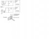
As per attached diagram , it's said that it can pull up 5v from PIC to 13v for Rs232 connection.But when i referred the MAX3222 datasheet, it's said that it can only pull up 3.5v to 5v.Then in such case , how it works?
Any help, please
Thanks
As per attached diagram , it's said that it can pull up 5v from PIC to 13v for Rs232 connection.But when i referred the MAX3222 datasheet, it's said that it can only pull up 3.5v to 5v.Then in such case , how it works?
Any help, please
Thanks
") It's amazing how many firms and devices actually get their serial devices to function with the liberties they take. Take for example the serial download circuit attached that connects the Picaxe series of micro controllers (PIC based). Note that the serial output from the Picaxe to the PC only switches between 0v and +5. By not passing through to -3v or more negative for the 'mark' state the circuit should not work reliably according to the standard, but in reality it seems to work very well as it's the only method to download a program to a Picaxe. There have been problems noted by some using laptops but that is most likely because of the PC to Picaxe direction not going as high positive as most desk top PCs. I've read that many laptops only switch at +/- 5 volts.
It's amazing how many firms and devices actually get their serial devices to function with the liberties they take. Take for example the serial download circuit attached that connects the Picaxe series of micro controllers (PIC based). Note that the serial output from the Picaxe to the PC only switches between 0v and +5. By not passing through to -3v or more negative for the 'mark' state the circuit should not work reliably according to the standard, but in reality it seems to work very well as it's the only method to download a program to a Picaxe. There have been problems noted by some using laptops but that is most likely because of the PC to Picaxe direction not going as high positive as most desk top PCs. I've read that many laptops only switch at +/- 5 volts.