I've been trying to connect my PC to a pic 16f88, and have it flip some LED's to indicate that a byte was recieved. I am without a MAX232 mostly for money issues(I know they are only a dollar fifty), but also because I feel the more descrete components I use the more I'll understand whats going on.
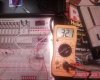
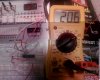
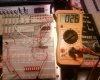
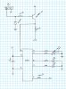
I've built a voltage shifter and inverter to match the required 0-5V voltage level and the active low, as is required in the data sheet. I had a cicruit that I designed origionally, but I found a more simple design online and used it.
I have the Pic sending the character 'A' so I could hook it up to the OSCOPE for comparison. When I hook the TX to the RX the led's flip back and forth, telling me that the program is working. I wrote it using MPLAB IDE C(code bellow).
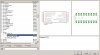
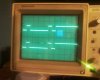
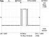
I have an OSCOP image of the raw serial output, which is -12 to +12(from a digital), and an image comparing the output from the chip to the output from the interface circuit(reading taken from the collector on the transistor without the pic attached time is 50uS and Volt is set to '5'). As far as I can see the timing and the voltage levels are the same.
I dont understand why the pic responds to itself, but wont respond to the PC..... HELP!!!
Thanks")
This is my first post ever, Im sorry if I left anything out, or formatted incorectly.
I've built a voltage shifter and inverter to match the required 0-5V voltage level and the active low, as is required in the data sheet. I had a cicruit that I designed origionally, but I found a more simple design online and used it.
I have the Pic sending the character 'A' so I could hook it up to the OSCOPE for comparison. When I hook the TX to the RX the led's flip back and forth, telling me that the program is working. I wrote it using MPLAB IDE C(code bellow).
I have an OSCOP image of the raw serial output, which is -12 to +12(from a digital), and an image comparing the output from the chip to the output from the interface circuit(reading taken from the collector on the transistor without the pic attached time is 50uS and Volt is set to '5'). As far as I can see the timing and the voltage levels are the same.
I dont understand why the pic responds to itself, but wont respond to the PC..... HELP!!!
Thanks
Code:
#include<pic.h>

main()
{
	char indicator=0;    //initilize variables
	char data=0;
	char flip=0;
	int delay=0;
	char output=0;

	TRISB=0;
	PORTB=0;

	TRISA=0;
	PORTA=0;

	OSCCON=0b01100000;   //4 Mhz
	RCSTA=0b10010000;    //  Set for N81
	TXSTA=0b00100100;    //
	SPBRG=25;            //  Set for 9600 baud

	PORTB=0b11111111;    // Flash all Led's to make sure the program made it that far
	PORTA=0b11111111;
	for(int x=0;x<20000;x++);  // delay so the flash can be noticed
	PORTB=0b00000000;
	PORTA=0b00000000;
	PORTA=0b11000000;   //Set LED's on for intial state.

	do
	{
		if((PIR1&0b00100000)==0b00100000)  // PIR1 bit 5 goes high when a char has successfully been recieved
		{
			if(flip)flip=0;  //Flip var flip to switch Led's
			else flip=1;

			data=RCREG;   //  Retrive data from RCREG to reset PAR1.5
		}

		if(delay==1000)  //Put Delay on transmit so OSCOPE can get a clean read and can confirm loop is running
		{
			TXREG='A';  // transmit 'A'
			delay=0;    // reset delay
		}

		if(flip)     //display to indicate that char has been recieved.
		{
			PORTA=0b11000000;
		}
		else
		{
			PORTA=0b00000011;
		}

		delay++;  //inc delay for transmit
	}
	while(1);     //infinite loop
}
This is my first post ever, Im sorry if I left anything out, or formatted incorectly.
Attachments
Last edited: