Continue to Site

Welcome to our site!

Electro Tech is an online community (with over 170,000 members) who enjoy talking about and building electronic circuits, projects and gadgets. To participate you need to register. Registration is free. Click here to register now.

  • Welcome to our site! Electro Tech is an online community (with over 170,000 members) who enjoy talking about and building electronic circuits, projects and gadgets. To participate you need to register. Registration is free. Click here to register now.

Rs-232, Pic Stepper Motor Interface?

Status
Not open for further replies.

perpetual_dream

New Member
HEY,
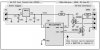
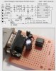
Id like to use pic to control a stepper motor. The input commands of the PIC should come through the RS-232 serial port. Ive seen the attached schematic online but I can't see where is the RS-232 input to the pic micro-controller... Can u help me plz? and if anyone has any relevant schematic diagram? your help is deeply appreciated
Thanks :)
 

Attachments

  • serial-stepper.gif
    serial-stepper.gif
    3.4 KB · Views: 1,400
Hi,

The schematic you posted does not show a PIC microcontroller...

Do you have a particular PIC in mind?

Regards, Mike
 
HEY,
THERE IS... THE PIC12C509 .... I'm intending to use the PIC16F628 OR PIC16F84 incase the 16f628 didn't arrive on time. I don't need a complicated functionality. All I need is to control the stepper from the computer using a microcontroller interface so I searched the internet and thought that the implementation of 12C509 would be similar... isn't it?
thanks for the reply...
 
Please forgive me... I missed that...

It seems pin 4 is being used to receive RS232 data... I've done this on 8 pin 12F675 and 12F683 devices utilizing bit-banged serial code but I used 2N7000 (BS170) N-channel MOSFETs for the interface...

Regards, Mike
 

Attachments

  • RS232 Circuit for 12F683.jpg
    RS232 Circuit for 12F683.jpg
    47.9 KB · Views: 2,053
  • RS-232 Circuit for 16F627A.jpg
    RS-232 Circuit for 16F627A.jpg
    46.3 KB · Views: 7,208
Last edited:
I'd hold out for the 628 as that has an async port, bitbang serial I/O is a bit of a pain, especially to debug. You'd only need the RX side of mike's circuits, by the way since your diagram did not show TX in use.
 
Does the original design look ok for you guys? It appears to be less compicated.... I can implement it on PIC16F628 or PIC16F84, TRUE?
THANKS AGAIN GUYS.....
 
philba said:
I'd hold out for the 628 as that has an async port, bitbang serial I/O is a bit of a pain, especially to debug. You'd only need the RX side of mike's circuits, by the way since your diagram did not show TX in use.

Bit banging serial is dead easy on a PIC, and not a pain at all, hardly any more complicated than using the USART.

HOWEVER! - it's still worth using the 16F628 and USART, as it means you don't waste processor cycles bit-banging the serial routines.

I've never got around to completing my stepper PIC tutorial yet (so much to do and so little time!), but essentially I used timer interrupts to do the stepping (with tables for the step patterns), and using a switch on an I/O pin to select half or full step modes. I did implement a bit-banged serial port though, and controlled it through that - although, as I said previously, using the USART in the 628 would be advantageous (my code was based on some old 16C84 code I wrote years ago - before the 628, or even the F84).

You should be aware though that the USART requires inverted data, so you need to use a MAX232, or similar interface, that inverts the data.
 
OK.... THANK U ALL GUYS....
Ive found the PIC application notes really helpful so 2sum up I can use the attached diagram with the PIC outputs being connected to the ULN 2803 instead of being connected to the LEDS? YES OR NO?
THANKS AGAIN FOR YOU ALL... U R BY BY FAR THE BEST HELPING FORUM ONLINE
 

Attachments

  • serial.JPG
    serial.JPG
    31.9 KB · Views: 1,029
perpetual_dream said:
OK.... THANK U ALL GUYS....
Ive found the PIC application notes really helpful so 2sum up I can use the attached diagram with the PIC outputs being connected to the ULN 2803 instead of being connected to the LEDS? YES OR NO?
THANKS AGAIN FOR YOU ALL... U R BY BY FAR THE BEST HELPING FORUM ONLINE

Yes you could, however you should be aware that the diagram you posted is a serious antique - in car terms it's not a model-T Ford, more a horse and cart!.

Check my tutorials for far more modern diagrams.
 
Nigel Goodwin said:
Bit banging serial is dead easy on a PIC, and not a pain at all, hardly any more complicated than using the USART.

maybe for you or me but for someone who hasn't done it before, it can be tricky. especially if it requires debugging. I'd rather recommend a path with as few complications as possible.
 
philba said:
maybe for you or me but for someone who hasn't done it before, it can be tricky. especially if it requires debugging. I'd rather recommend a path with as few complications as possible.
Philba,

T'was a fun learning experience for me but it does require some time and effort...

Not to worry... Should you ever find yourself in a position where a little 8-pin 12F675 or 12F683 would fit the bill and you need reliable bit-banged half-duplex or full-duplex serial I/O, with 16 byte circular Rx and Tx buffers no less, please don't hesitate to ask... You can also do half-duplex I/O using a single pin...

Kind regards, Mike
 

Attachments

  • RS232 Parasitic Power #2.JPG
    RS232 Parasitic Power #2.JPG
    73.7 KB · Views: 2,059
Status
Not open for further replies.

Latest threads

New Articles From Microcontroller Tips

Back
Top