Electro Tech is an online community (with over 170,000 members) who enjoy talking about and building electronic circuits, projects and gadgets. To participate you need to register. Registration is free. Click here to register now.
Welcome to our site! Electro Tech is an online community (with over 170,000 members) who enjoy talking about and building electronic circuits, projects and gadgets. To participate you need to register. Registration is free. Click here to register now.
direct translation would be 'disconnector'. It is the input for a reed switch wich gets closed every time the wheel (of wich you want an RPM count) does 1 rotation.
It's commonly used, a small magnet on the wheel and a reed switch, every time the magnet comes in front of the reed switch it closes, so you can count rotations.
I think they mean the points in the distributor, which are very rare these days. Most cars have electronic ignition and no more breaker points. I can see there is a possibility to select 4, 6 or 8 cylinder engines on the CD4018 pin 1, 11, 6 and 4. You can adapt the input to most any source of pulse and the decade to in the interval needed. A phototransistor and a piece of reflective tape will probably work. Maybe just remove the CD4046 and the CD4018 then let the pulse go directly to the clock (pin11) on the 74C925? These two ICs are there just to compensate for the way a four-stroke engine works and with different number of cylinders I think. What do you think?
I think they mean the points in the distributor, which are very rare these days. Most cars have electronic ignition and no more breaker points. I can see there is a possibility to select 4, 6 or 8 cylinder engines on the CD4018 pin 1, 11, 6 and 4. You can adapt the input to most any source of pulse and the decade to in the interval needed. A phototransistor and a piece of reflective tape will probably work. Maybe just remove the CD4046 and the CD4018 then let the pulse go directly to the clock (pin11) on the 74C925? These two ICs are there just to compensate for the way a four-stroke engine works and with different number of cylinders I think. What do you think?
I dunno the application of this circuit, and that schematic that was given is definitly for a car, so I'm just gonna assume it's for a car.
IMO, it would be too hard to get it the diode positioned.
What you need is to find a way to sense when a spark plug fires. I'm not sure how the sensor work exactly, but my friend has a digital tach on his go-kart and the lead just cable tied onto the plug wire.
I also had an anlog tach for my 86 Chevy Celebrity, the sensor for that connected to the untransformed end of the coil (it had a distributor). the tach also had a switch for 4,6,8 cylinders.
If it's for a car without a distributer, all you have to do is sense when the #1 cylinder fires and multiply by 4 (4 revolutions per cycle).
I'd suggest trying to find a different schematic...
I want to make a rpm meter for my metal lathe.Could I use a proximaty switch for an input. I have a prox swithch that will give an output of 10-30vdc. Maybe I can hook it to a hi-speed solid state relay to close for every rotation of the lathe spindle? 0-4000 rpm. :?:
A microcontroller with an LCD display would be far, far simpler.
Depends on what you mean by proximity switch. As far as a common magnetic reed switch, probably not, it's slow and probably not rated for millions of cycles. Now a Hall effect sensor would do just fine. That's what gets used for most RPM sensing, and they're dirt cheap. Also you could make an optical sensor, but don't get sawdust on the sensor.
I do not see why you need a solid state relay at all. The sensor's ground will be tied to the rest of the circuit ground so you need no isolation. The relay is too slow to use for signal isolation (also far too large and expensive!)- you'd just use a cheap optoisolator which comes in a DIP pkg.
You have not provided any additional information? You have not stated what your tachometer speed signal upper frequency will be. You have not stated your power supply voltages?
I suggest you read and understand the data sheets, then make a drawing or schematic and post it. Much more information is needed from you.
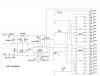
i want to use this circuit for bike 1 cylinder and i don't know what frequency to use.voltage supply for the bike is 12V. here I attach the circuit I built I had tried and failed. and I ask your good offices to help me identify the problem circuit.
I looked at the drawing you posted. I followed the link and printed the Word document. I can't make out the drawing. It is like fuzzy and out of focus. What I could make out looks pretty straight forward. I just can't focus enough to read the damn thing. Sorry. Maybe someone else will come along that can read the schematic and see it better than I can.
What part of what you have built does not work? Does the F to V work? You should be able to troubleshoot that wioth a meter.
I can't read it either, and it is very fuzzy, but I can see it well enough to tell you that the chips (other than the voltage regulator) are 2 LM3914s and one LM2917, if that helps.
Oh, but the title of the thread already tells us that. Doh! Never mind ...
F to V to function properly but the LM3914 is a problem. I did not get the reading. I hope if you are in for other circuit to work properly, maybe you can show me. I'm almost out of time to this project.'s Head was dizzy . lol!
I don't know how you managed to get that image into Word, but all I know is that's the worst way to try to convey graphic information. Please try to post a readable version of the schematic so we can actually see it. That should help some of the experts here diagnose your problem.
apologize for this inconvenience. I have been searching the internet, can I use this circuit for the engine 1 slinder? This circuit is suitable and right for my use? so, thank you.
This site uses cookies to help personalise content, tailor your experience and to keep you logged in if you register.
By continuing to use this site, you are consenting to our use of cookies.