riccardo
Member
Hi,
I have been playing with a Royer type circuit. (I think its actually a "collector resonance oscillator" since there's not feedback winding like in a Royer) and have noticed a couple of versions on-line and was wondering about the differences.
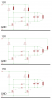
In the attached image;
The top circuit uses two chokes and resonates the LC load.
The middle circuit uses a single choke to resonate an LC load with a centre tapped coil.
The bottom circuit is like the first but with one choke removed. Or as the second with the choke connecting to one side of the LC load instead of a centre tap.
I basically just tried the third version to see what would happen, and it seems to work just fine. Whichever side the choke goes it seems to just work.
My question is what is the advantage of the two choke version (top) when using just one (bottom) seems to work the same?
I have been playing with a Royer type circuit. (I think its actually a "collector resonance oscillator" since there's not feedback winding like in a Royer) and have noticed a couple of versions on-line and was wondering about the differences.
In the attached image;
The top circuit uses two chokes and resonates the LC load.
The middle circuit uses a single choke to resonate an LC load with a centre tapped coil.
The bottom circuit is like the first but with one choke removed. Or as the second with the choke connecting to one side of the LC load instead of a centre tap.
I basically just tried the third version to see what would happen, and it seems to work just fine. Whichever side the choke goes it seems to just work.
My question is what is the advantage of the two choke version (top) when using just one (bottom) seems to work the same?